Fluid flow monitor

a technology of flue gas monitor and flow monitor, which is applied in the direction of liquid/fluent solid measurement, force measurement using piezo-resistive materials, instruments, etc., can solve the problems of increasing the risks of multiple manipulations and entry of iv sites

Active Publication Date: 2010-08-17
HONEYWELL INT INC
View PDF10 Cites 53 Cited by
  • Summary
  • Abstract
  • Description
  • Claims
  • Application Information

AI Technical Summary

Benefits of technology

[0008]The aforementioned aspects and other objectives and advantages can now be achieved as described herein. A differential force sensor apparatus and method for automatically monitoring manual injections through an intravenous line is disclosed. The differential force sensor includes two piezoresistive sense die packaged in close proximity utilizing any one of a number of packaging processes. The two piezoresistive sense die can be utilized to measure force exerted on a diaphragm on either side of an orifice. The piezoresistive sense die can be packaged in close proximity to make intimate contact with a diaphragm(s) located on either side of the orifice. The differential force sensor further includes one or more plungers that make intimate contact with the diaphragm and transfer the force to the piezoresistive sense die. Additionally, one or more ASIC components and microcontrollers can be utilized to provide thermal calibration and differential calculation.

Problems solved by technology

Each manual step in such procedures increases the risks associated with multiple manipulations and entry of IV sites.

Method used


Image

  • Fluid flow monitor
  • Fluid flow monitor
  • Fluid flow monitor

Examples


first embodiment

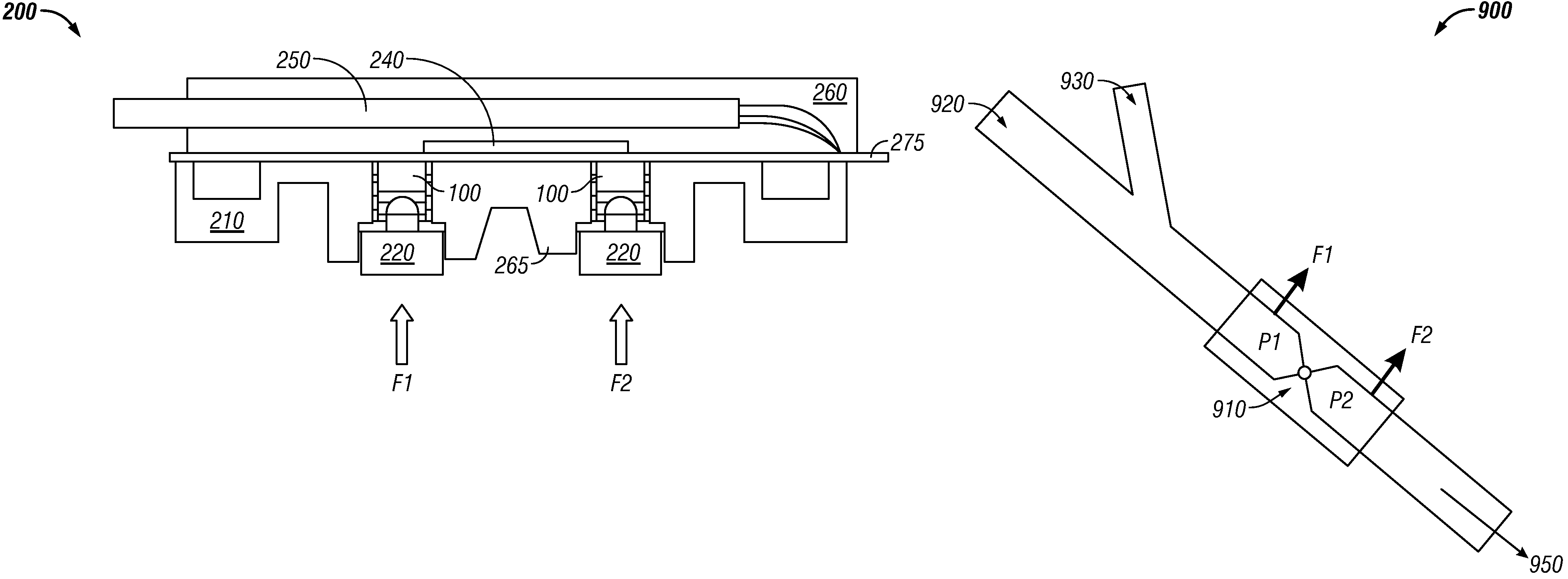
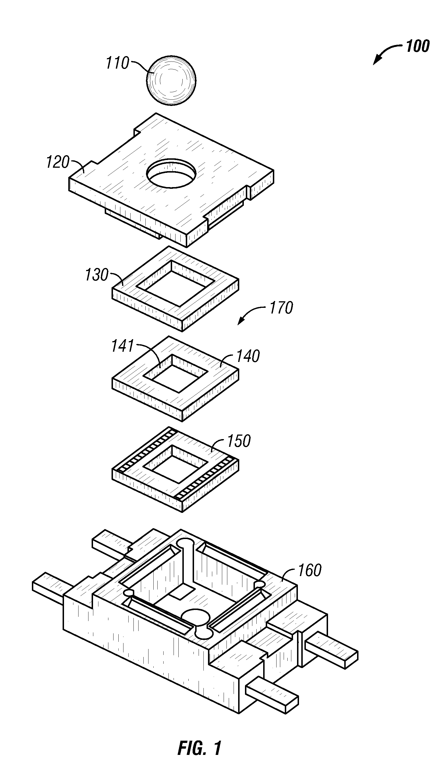
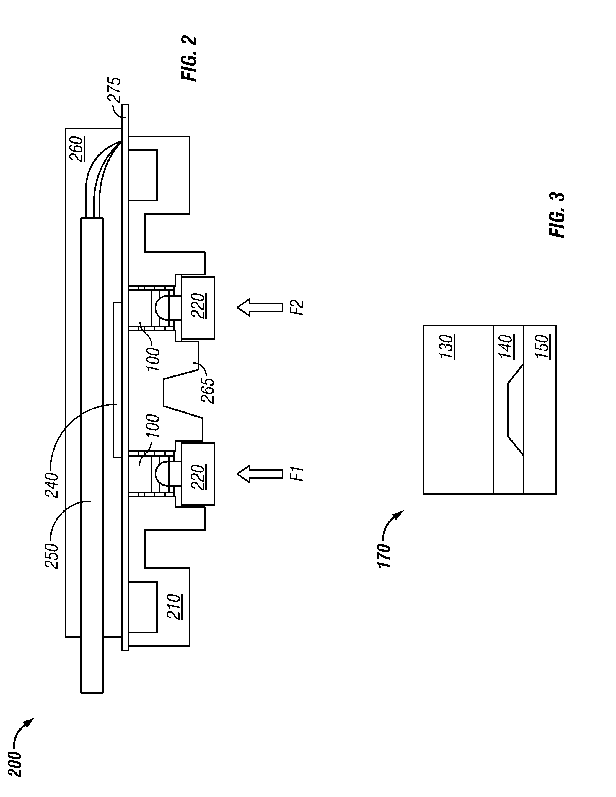
[0025]FIG. 2 illustrates a cross-sectional view of a differential force sensor 200 with two force sensors 100 each packaged by means of a conductive seal stack 170, in accordance with a Note that in FIGS. 1-9, identical or similar parts or elements are generally indicated by identical reference numerals. The two force sensors 100 can be packaged by means of a conductive seal stack 170, which includes the conductive seal 150 and the environmental seal 130, as depicted in FIG. 1. The force sensors 100 can be placed on a PCB (Printed Circuit Board) 275 and held captive by a single piece of plastic housing 265. The single plastic housing 265 includes two plungers 220 that make intimate contact with a flow diaphragm (not shown) and transfer the force into the piezoresistive sense die 140 associated with the force sensors 100. The differential force sensors 100 can be covered with a bottom cover 210 and a top cover 260.

[0026]FIG. 3 illustrates an exploded view of the conductive seal stac...

second embodiment

[0027]FIG. 4 illustrates an exploded view of a force sensor 400 with piezoresistive sense die 140 glued to a printed circuit board (PCB) 460, in accordance with a The piezoresistive sense die 140 can be glued to the PCB 460 by means of glue 450. The differential force sensor 400 features an integrated circuit sensor element in the form of piezoresistive sense die 140 and the PCB 460 in a small plastic housing 425. Such a sensor 400 with extremely small size enables the use of multiple sensors in limited available space. Such package also provides excellent corrosion resistance and isolation to external package stress. The differential force sensor 400 comprises a dual amplifier 480 bonded to the PCB 460 utilizing an epoxy 465. A cover 405 can be placed over the sensor 400 in order to provide an environmental seal. The molded housing 425 can be positioned over the sense die 140 utilizing an epoxy 440, whereby a gel 420 can be dispensed and cured into the orifice 910 above the sense ...

third embodiment

[0030]FIG. 6 illustrates a cross-sectional view of a differential force sensor 600 with two piezoresistive sense die 140 each glued to a carrier 610, which can be implemented in accordance with a Again as reminder, in FIGS. 1-9 identical or similar parts or elements are generally indicated by identical reference numerals. The piezo-resistive sense die 140 can be glued to the carrier 610 and the gel 420 can be dispensed into the orifice 910 in the carrier 610 which allows the gel 420 to make intimate contact with the back side (etched side) of the sense die 140. The carrier assembly 610 can be glued to the PCB 460 so that the sense die 140 can be electrically connected.

[0031]The diaphragm 415 can be placed over the cured gel 420 and a protective cover 620 can be placed over the gel 420 to hold the diaphragm 415 in place and provide an environmental seal. The differential force sensor 600 further comprises a top housing 260 that contains strain relief and a bottom housing 210 that ho...


PUM


Abstract

A differential force sensor method and apparatus for automatically monitoring manual injections through an intravenous line. The differential force sensor includes two piezoresistive sense die that are packaged in close proximity utilizing a number of packaging processes. The two piezoresistive sense die can be utilized to measure forces exerted on a diaphragm on either side of an orifice. The piezoresistive sense die can be packaged in close proximity to make intimate contact with the diaphragms on either side of the orifice. The differential force sensor further includes two plungers that make intimate contact with the diaphragm and transfer the force into the piezo-resistive sense dies. Additionally, one or more ASICs and microcontrollers can be utilized to provide thermal calibration and differential calculation.

Description

TECHNICAL FIELD[0001]Embodiments are generally related to sensor methods and systems. Embodiments are also related to differential force sensors. Embodiments are additionally related to differential force sensors utilized in the context of monitoring manual patient injections through an intravenous line.BACKGROUND OF THE INVENTION[0002]In the medical field, it is common for intravenous (IV) medications such as, for example, antibiotics, antiviral, antiemetic, chemotherapy, and so forth, to be administered intermittently with a frequency as often as multiple times per day. Depending on the frequency of administration, the patient is either repeatedly connected to and disconnected from an IV line or is continuously connected to an IV line between administrations. In either case, the intermittent medications are generally administered by trained personnel utilizing predefined procedures that often include a series of manual steps and a large number of disposable supplies. Each manual s...

Claims


Application Information

Patent Timeline
Patent Type & Authority Patents(United States)
IPC IPC(8): G01F1/37A61M31/00
CPCA61M5/14G01F1/383G01L19/0023G01L1/2231G01L9/0055G01L15/00G01L1/18A61M5/16831A61M2205/332A61M5/168
Inventor ECKHARDT, TODDWADE, RICHARDJONES, RYAN
Owner HONEYWELL INT INC
Why Eureka
Try Eureka