
Reflective screens

a technology of reflected screen and screen body, which is applied in the direction of projectors, shutters, instruments, etc., can solve the problems of less workability of screens, reduced image contrast due to reflected environmental light, and still suffer from system and structure drawbacks

Active Publication Date: 2010-08-17
DELTA ELECTRONICS INC
View PDF14 Cites 39 Cited by
  • Summary
  • Abstract
  • Description
  • Claims
  • Application Information

AI Technical Summary

Benefits of technology

The patent describes a reflective screen that has a layer to absorb light and create a shift in color when light is reflected. The screen also has a layer to filter the light and a layer to scatter the light. The technical effect of this design is that it allows for more precise and accurate color representation in a reflective screen.

Problems solved by technology

Reflective screens, however, have same drawbacks, such as reduced image contrast due to reflected environmental light.
Environmental light must be polarized prior to increasing the image contrast of the screen, thus, the screen is less workable.
Although the above-mentioned conventional reflective screens may increase image and color contrast, they still suffer from some drawbacks in system and structure.

Method used


Image

  • Reflective screens
  • Reflective screens
  • Reflective screens

Examples


Embodiment Construction

[0026]The following description is of the best-contemplated mode of carrying out the invention. This description is made for the purpose of illustrating the general principles of the invention and should not be taken in a limiting sense. The scope of the invention is best determined by reference to the appended claims.

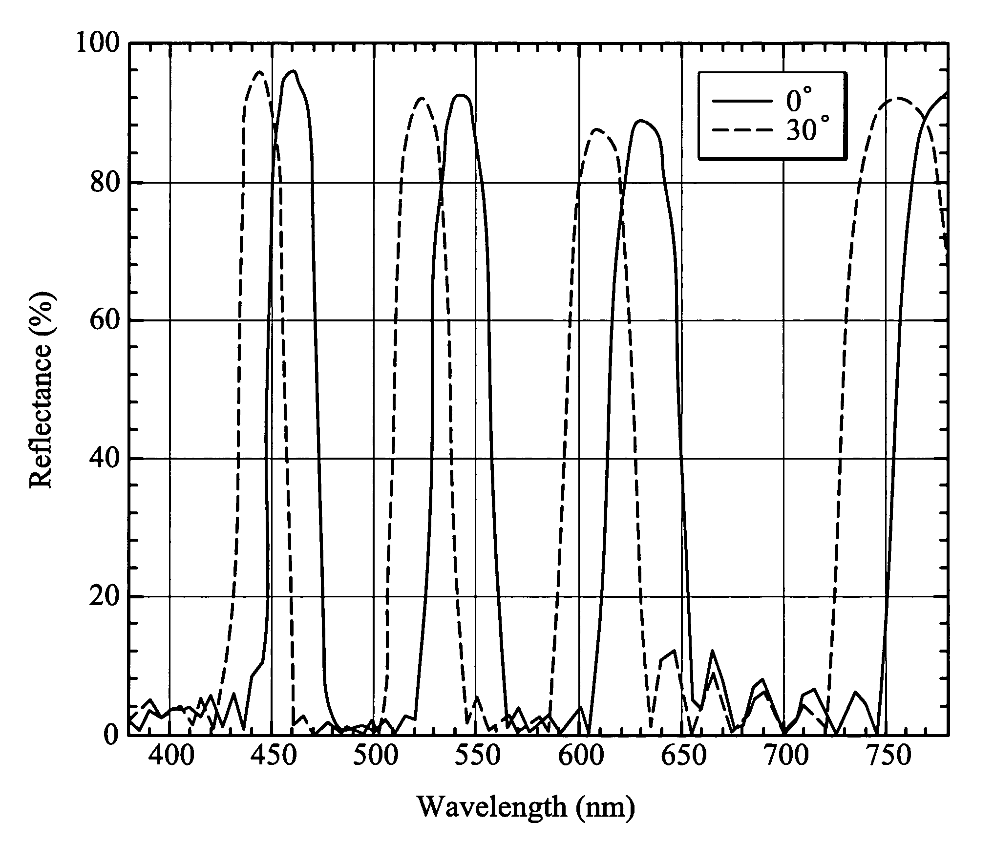
[0027]FIG. 3 is a schematic view showing a reflective screen according to an embodiment of the invention. Referring to FIG. 3, a reflective screen according to an embodiment of the invention comprises a diffusion layer 103, a cap layer 101, an interference filter 102 and an absorption layer 104 which are sequentially disposed (on the cap layer 101) along the incident direction of light. Image signals projected on the reflective screen consist of the three primary colors, i.e. red (R), green (G) and blue (B). In addition to the image signals, white environmental light (W) is projected on the reflective screen. The interference filter 102 includes alternate layers of hig...


PUM


Abstract

This invention discloses a projection screen including a diffusion layer, a cap layer, an interference layer and an absorption layer. The projection screen of this invention is based on the concept of inverse reflection. The interference filter includes a plurality of high and low refractive index layers, both of which alternately stacked. The projection screen conveys a small spectral shift and a narrow bandwidth at different incident angles so that the better contract ratio of the image signal can be displayed.

Description

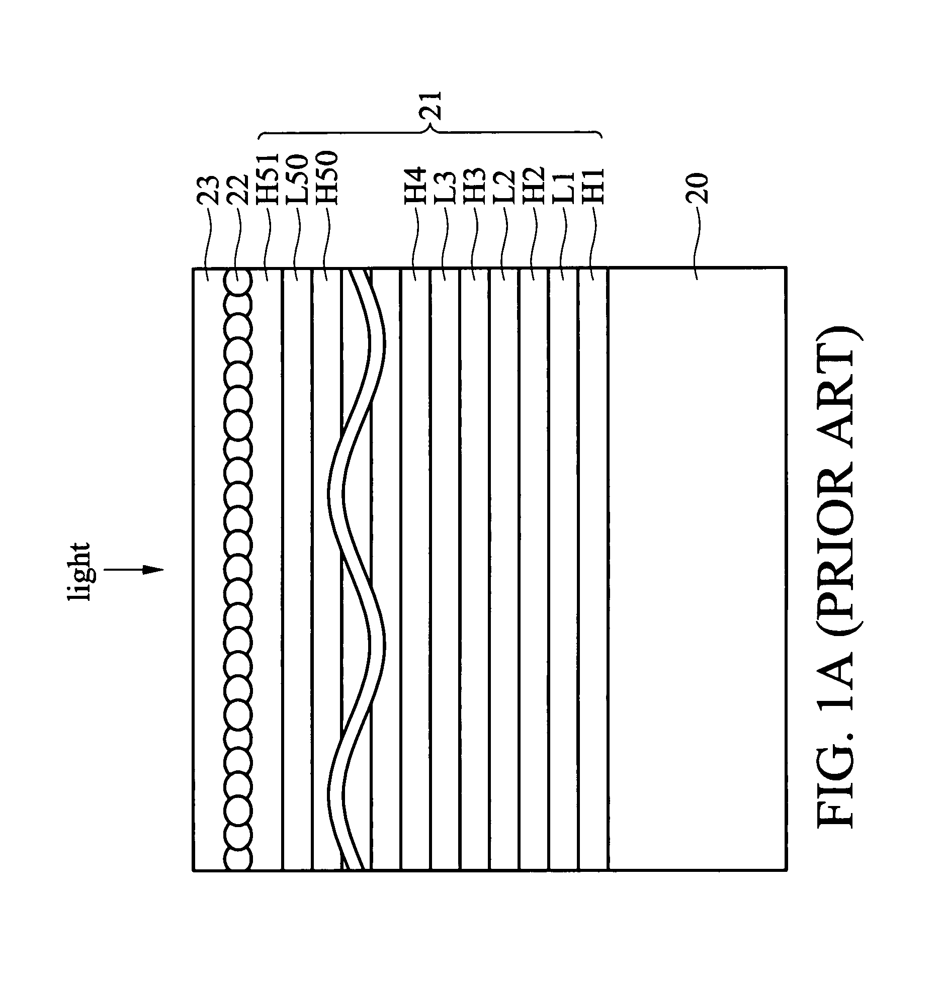
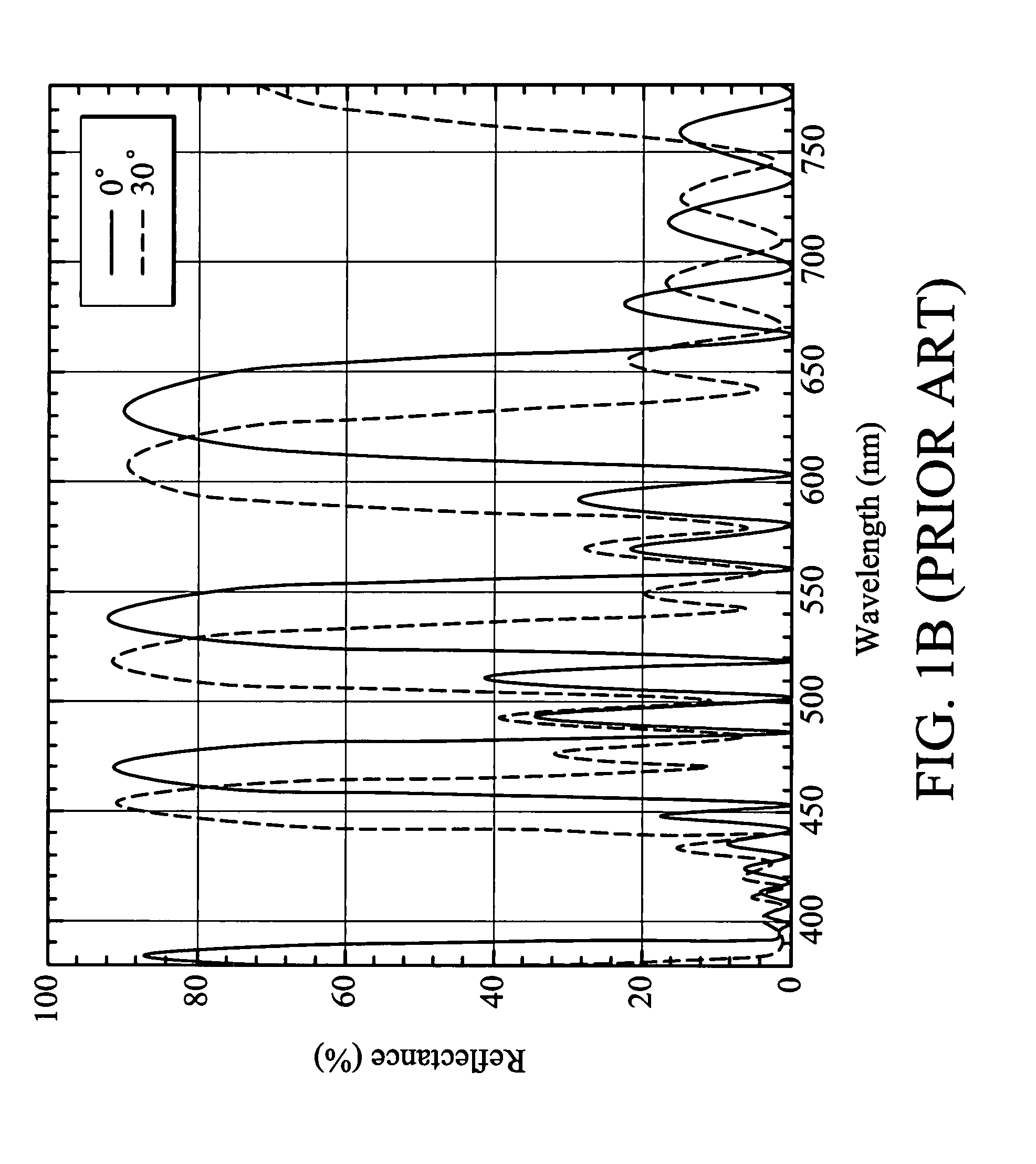
BACKGROUND OF THE INVENTION[0001]1. Field of the Invention[0002]The invention relates to a reflective screen for projectors, and more particularly to a reflective screen capable of increasing image contrast.[0003]2. Description of the Related Art[0004]A front projection display, referred to as a projector, typically uses a reflective screen to display images. Image signals projected on and reflected by the reflective screen are seen by viewers as images. Conventional reflective screens typically comprise flexible material, thus, they are easily rolled up for storage. Reflective screens, however, have same drawbacks, such as reduced image contrast due to reflected environmental light.[0005]Recent improvements in reflective screens include increased image contrast in bright environmental light, increasing flexibility and durability, and reduced fabrication costs.[0006]U.S. Pat. No. 5,335,022 discloses a screen with a high image contrast. The screen selects polarized optical signals fr...

Claims


Application Information

Patent Timeline
Patent Type & Authority Patents(United States)
IPC IPC(8): G03B9/08
CPCG02B5/0226G02B5/0284G02B5/286G03B21/567
Inventor HO, FANG-CHUANHUANG, JUNE-JEITU, KUN-HUNG
Owner DELTA ELECTRONICS INC
Learn More