Clock generator and data recovery circuit using the same
a clock generator and data recovery technology, applied in pulse automatic control, digital transmission, angle demodulation by phase difference detection, etc., can solve the problem of longer tracking time and failure to timely reach the optimal sampling phase. , to achieve the effect of shortened tracking tim
- Summary
- Abstract
- Description
- Claims
- Application Information
AI Technical Summary
Benefits of technology
Problems solved by technology
Method used
Image
Examples
first embodiment
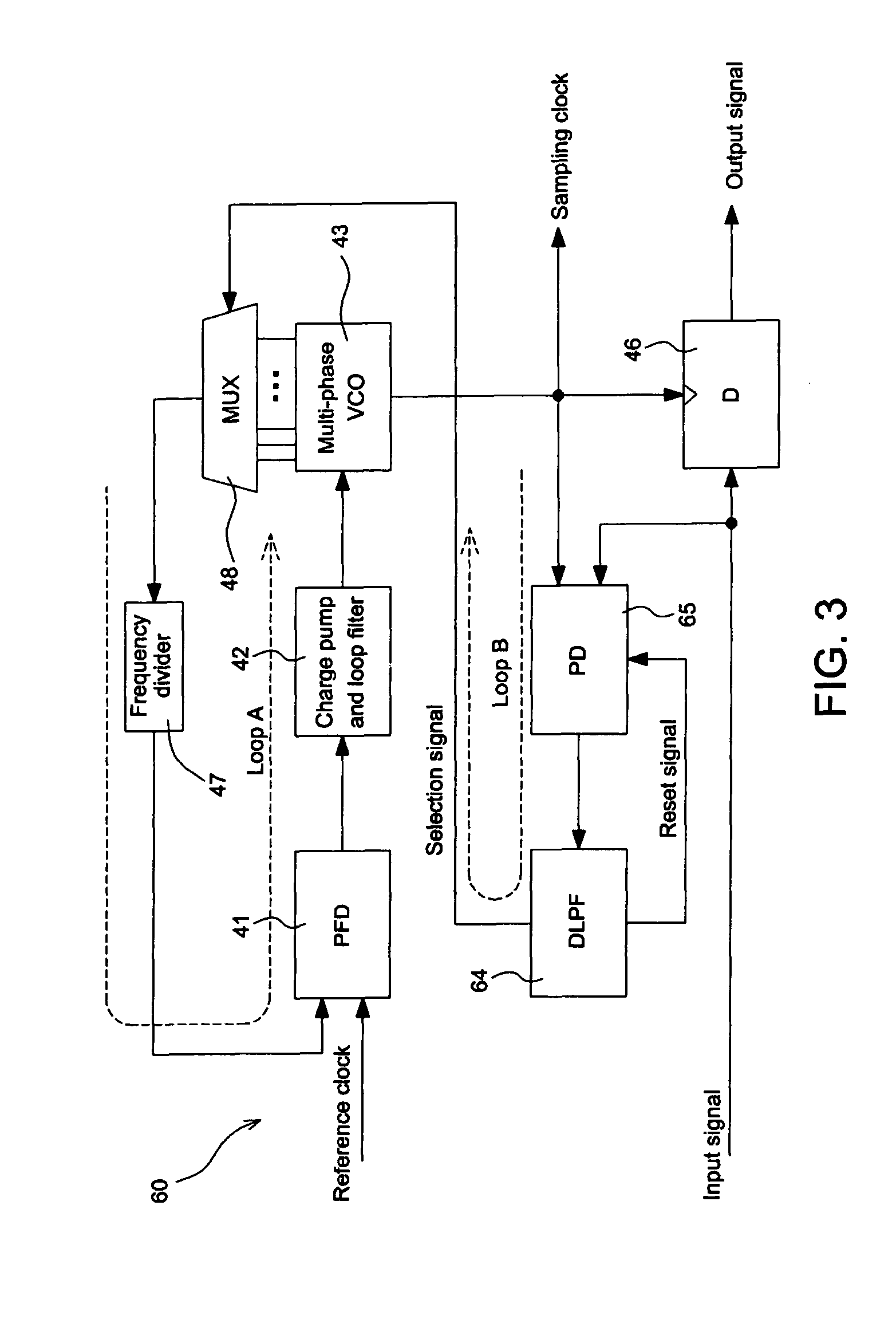
[0021]FIG. 3 shows a feedback-based data recovery circuit according to the invention. Referring to FIG. 3, the recovery circuit 60 includes a voltage controlled oscillation loop (loop A in FIG. 3), a data recovery loop (loop B in FIG. 3), and a D-type flip-flop 46. The voltage controlled oscillation loop includes a phase-frequency detector (PFD) 41, a charge pump and loop filter 42, a multi-phase voltage controlled oscillator (multi-phase VCO) 43, a multiplexer 48, and a frequency divider 47. The data recovery loop (loop B in FIG. 3) includes a digital low-pass filter (DLPF) 64 and a phase detector (PD) 65. The implementation and realization of each of the elements in FIG. 3 is well known to those of ordinary skill in the art, and is as described in Larsson. Detailed descriptions are therefore herein omitted.
[0022]The digital low-pass filter 64 of the recovery circuit 60 has the function of resetting and clearing the values temporarily stored in the phase detector 65. In addition to...
second embodiment
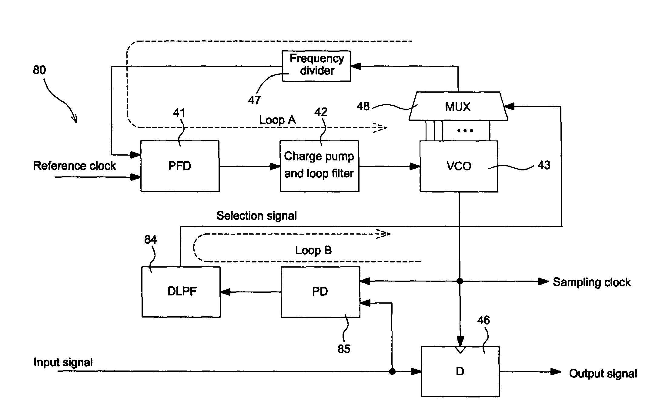
[0027]FIG. 5 shows a feedback-based data recovery circuit according to the invention. As shown in FIG. 5, the recovery circuit 80 is similar to the recovery circuit 60 of FIG. 3 except that a phase detector 45 does not have the reset function and a digital low-pass filter 84 does not output the reset signal.
[0028]FIG. 6 shows an embodiment digital low-pass filter design 84 of FIG. 5 using MATLAB code. In this embodiment, the signal “out” represents the selection signal, the parameter acc(n) represents the accumulated phase error, the parameter acctime(n) represents the accumulated time, the parameter N represents the phase adjustment amount in each adjustment, the parameter K represents the threshold phase difference, and the parameter Stoptime represents the stop accumulating time. As shown in FIG. 6, the program is divided into two parts. The first part 91 starts to accumulate the accumulated phase error acc(n) after the accumulated time acctime(n) exceeds the stop accumulating ti...
PUM
 Abstract
Description
Claims
Application Information
 - R&D
- Intellectual Property
- Life Sciences
- Materials
- Tech Scout
- Unparalleled Data Quality
- Higher Quality Content
- 60% Fewer Hallucinations
Browse by: Latest US Patents, China's latest patents, Technical Efficacy Thesaurus, Application Domain, Technology Topic, Popular Technical Reports.
© 2025 PatSnap. All rights reserved.Legal|Privacy policy|Modern Slavery Act Transparency Statement|Sitemap|About US| Contact US: help@patsnap.com


