Opening and closing assembly, and multifunction device including the assembly

a technology of opening and closing assembly and assembly, which is applied in the direction of electrographic process equipment, instruments, printing, etc., can solve the problem of pivoted cover body, and achieve the effect of smooth and quick opening

Inactive Publication Date: 2010-08-17
BROTHER KOGYO KK
View PDF5 Cites 50 Cited by
  • Summary
  • Abstract
  • Description
  • Claims
  • Application Information

AI Technical Summary

Benefits of technology

[0014]In the multifunction device, it is preferable that the image reading unit can be smoothly and quickly opened relative to the image recording unit, for facilitating the above-described maintenance work.
[0016]The present invention was made in view of the background prior art discussed above. It is therefore a first object of the invention to provide an opening and closing assembly in which a load applied against a pivot motion of a second casing body relative to a first casing body is increased in a closing transition from an open position of the second casing body to a closed position of the second casing body and is reduced in an opening transition from the closed position to the open position, namely, in which the second casing body can be smoothly and quickly opened relative to the first casing body while the second casing body is prevented from being rapidly closed relative to the first casing body. It is a second object of the invention to provide a multifunction device including the opening and closing assembly which has the above-described technical advantage. The first and second objects may be achieved according to first and second aspects of the invention, respectively, which are described below.
[0018]The opening and closing assembly constructed according to the present invention is advantageous, for example, where the gripped portion of the distal end portion of the support stand is wedged into between the first and second wall portions by a larger extent during a closing transition from the open position of the second casing body to the closed position of the second casing body during which the distant portion of the second casing body is forced in a direction toward the distant portion of the first casing body, than during an opening transition from the closed position to the open position during which the distant portion of the second casing body is forced in a direction away from the distant portion of the first casing body. That is, when the second casing body is being closed relative to the first casing body, a relatively large frictional force is generated between the gripped portion of the distal end portion of the support stand and each of the first and second wall portions of the above-described other of the first and second casing bodies, whereby the second casing body is prevented, owing to the large frictional force, from being rapidly pivoted relative to the first casing body in its closing direction. It is therefore possible to prevent a hand of an operator from being caught between the first and second casing bodies when the operator intends to place the second casing body into its closed position relative to the first casing body. On the other hand, when the second casing body is being opened relative to the first casing body, a relatively small frictional force is generated between the gripped portion of the distal end portion of the support stand and each of the first and second wall portions of the above-described other of the first and second casing bodies, whereby the second casing body can be easily pivoted relative to the first casing body in its opening direction.
[0020]In this advantageous arrangement, when the second casing body is being closed relative to the first casing body, the frictional force generated between the gripped portion of the distal end portion of the support stand and each of the first and second wall portions of the above-described other of the first and second casing bodies can be made larger than in an arrangement in which the contact surface of the gripped portion is not provided by the high friction portion. Therefore, the second casing body can be more reliably prevented from being rapidly pivoted relative to the first casing body in its closing direction, thereby making it possible to more reliably prevent a hand of an operator from being caught between the first and second casing bodies when the operator intends to place the second casing body into its closed position relative to the first casing body.
[0022]In this another advantageous arrangement, when the gripped portion of the distal end portion of the support stand is gripped between the first and second wall portions of the above-described other of the first and second casing bodies, a contact area of the gripped portion, which is held in contact with the first and second wall portions, can be made larger than in an arrangement in which the distance between the first and second wall portions is constant. The increase in the contact area of the gripped portion leads to an increase in the frictional force generated between the gripped portion of the distal end portion of the support stand and each of the first and second wall portions of the above-described other of the first and second casing bodies when the second casing body is being closed relative to the first casing body. Therefore, the second casing body can be more reliably prevented from being rapidly pivoted relative to the first casing body in its closing direction, thereby making it possible to more reliably prevent a hand of an operator from being caught between the first and second casing bodies when the operator intends to place the second casing body into its closed position relative to the first casing body.

Problems solved by technology

Therefore, a large force is required to cause the cover body to be pivoted relative to the casing body.

Method used


Image

  • Opening and closing assembly, and multifunction device including the assembly
  • Opening and closing assembly, and multifunction device including the assembly
  • Opening and closing assembly, and multifunction device including the assembly

Examples


Embodiment Construction

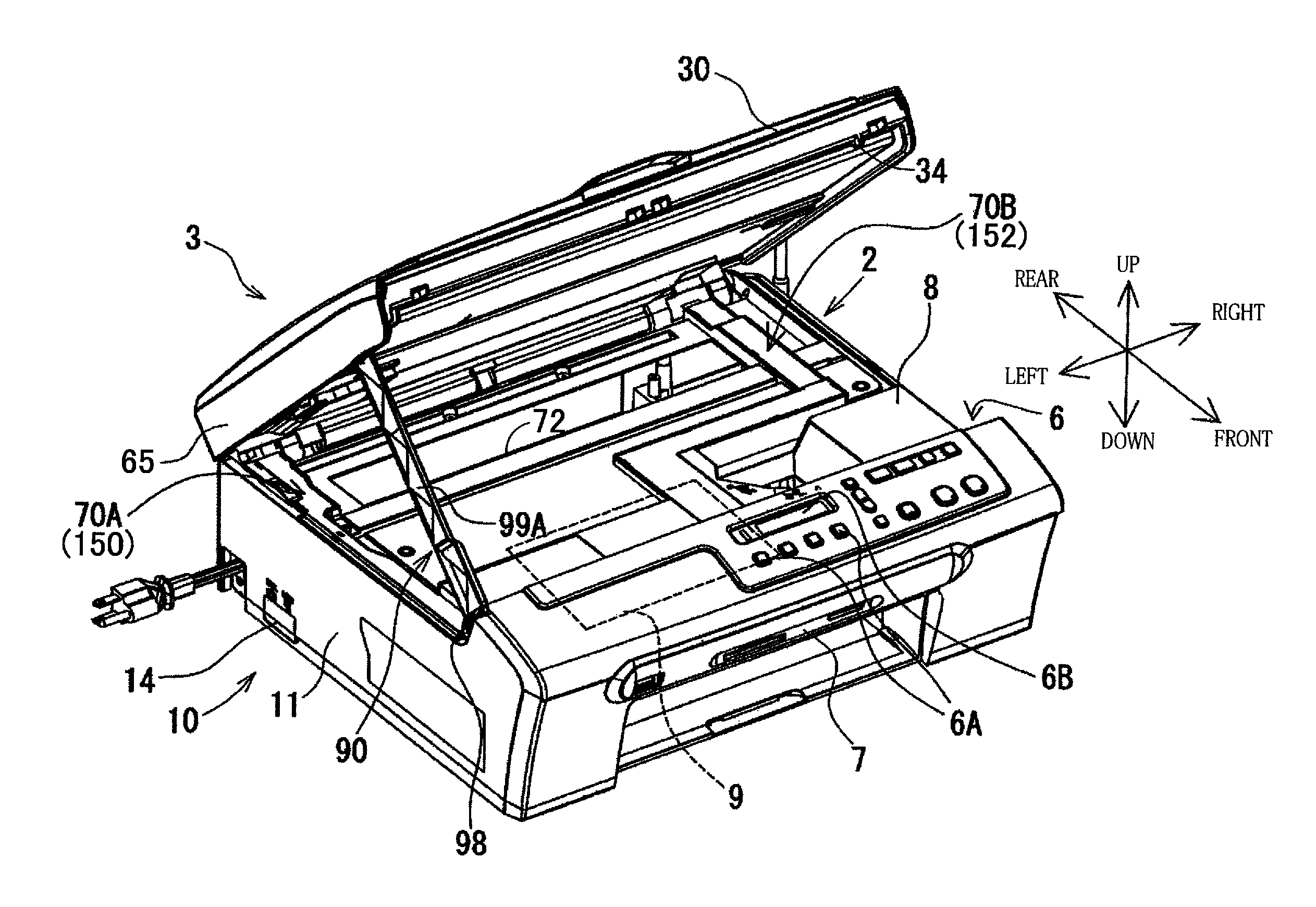
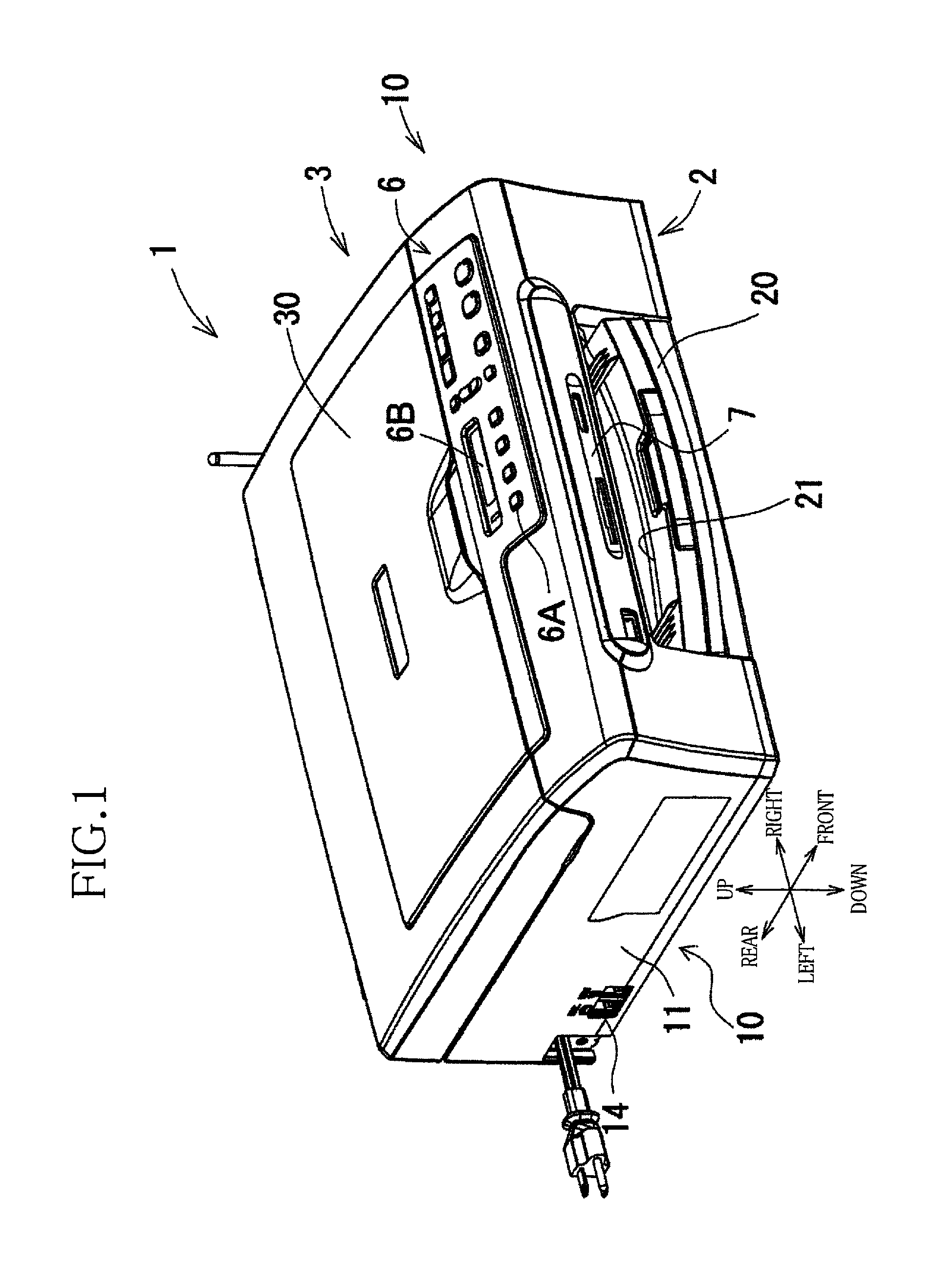
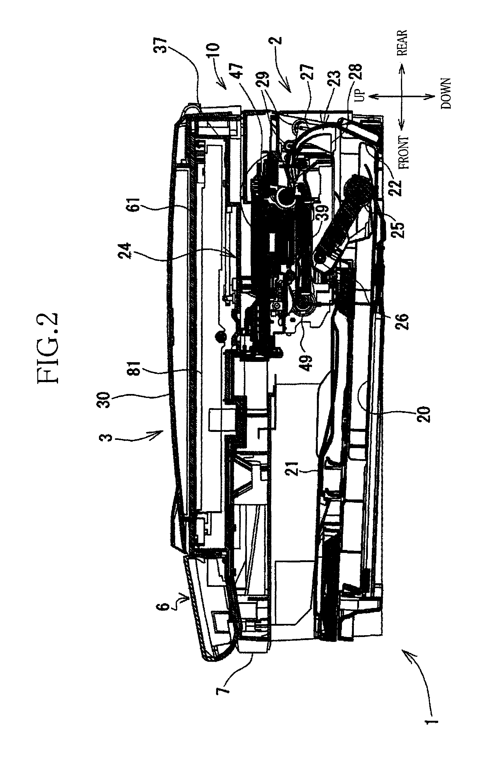
[0046]Referring to the accompanying drawings, there will be described an opening and closing assembly in the form of a multifunction device (MFD) 1 that is constructed according to an embodiment of the present invention. The multifunction device 1 is arranged to perform various functions such as printer, scanner, copier, telecommunication and facsimile functions. As shown in FIG. 1, the multifunction device 1 has a main body 10 that is provided by a generally rectangular parallelepiped body. A height of the main body 10 is smaller than a width and a depth of the main body 10. The main body 10 has a first casing body in the form of a printer unit 2 and a second casing body in the form of a flatbed scanner unit (hereinafter referred to as FBS unit) 3. The printer unit 2 serves as an image recording unit for recording an image onto a recording medium, while the FBS unit 3 superposed on the printer unit 2 serves an image reading unit for reading an image carried on an original. In the f...


PUM


Abstract

An opening and closing assembly includes: (a) a first casing body; (b) a second casing body pivotable to be selectively placed in open and closed positions relative to the first casing body; and (c) a support stand for supporting the second casing body to maintain the open position. The support stand includes (c-1) a proximal end portion pivotably connected to one of the first and second casing bodies and (c-2) a distal end portion slidably connected to the other of the first and second casing bodies. The other of the first and second casing bodies includes (i) a guide portion for guiding the distal end portion of the support stand, and (ii) first and second wall portions cooperating with each other for gripping the distal end portion of the support stand. The distal end portion of the support stand includes a gripped portion having a thickness that is increased in a direction away from the distal end portion of the support stand toward the proximal end portion of the support stand.

Description

[0001]This application is based on Japanese Patent Application No. 2006-168841 filed on Jun. 19, 2006, the content of which is incorporated hereinto by reference.BACKGROUND OF THE INVENTION[0002]1. Field of the Invention[0003]The present invention relates to an opening and closing assembly including an opening and closing mechanism and first and second casing bodies pivotable relative to each other, wherein the opening and closing mechanism is capable of maintaining an open position of the second casing body relative to the first casing body and opening and closing the second casing body relative to the first casing body in suitable manners.[0004]2. Discussion of Related Art[0005]Conventionally, there have been proposed various kinds of structures each of which is to be incorporated in an opening and closing assembly including first and second casing bodies pivotable relative to each other through a hinge and each of which is arranged to maintain an open position of the second casin...

Claims


Application Information

Patent Timeline
Patent Type & Authority Patents(United States)
IPC IPC(8): G03G15/00G03G21/16B41J29/13
CPCG03G21/16G03G2221/169G03G21/1628
Inventor IIJIMA, SHOTA
Owner BROTHER KOGYO KK
Why Eureka
Try Eureka