Article transport facility
a technology for transporting facilities and objects, applied in the direction of conveying, transportation and packaging, cranes, etc., can solve the problems of enlarging the installation space and complicating the construction, and achieve the effect of simplifying construction and reducing the number of components installed
- Summary
- Abstract
- Description
- Claims
- Application Information
AI Technical Summary
Benefits of technology
Problems solved by technology
Method used
Image
Examples
first embodiment
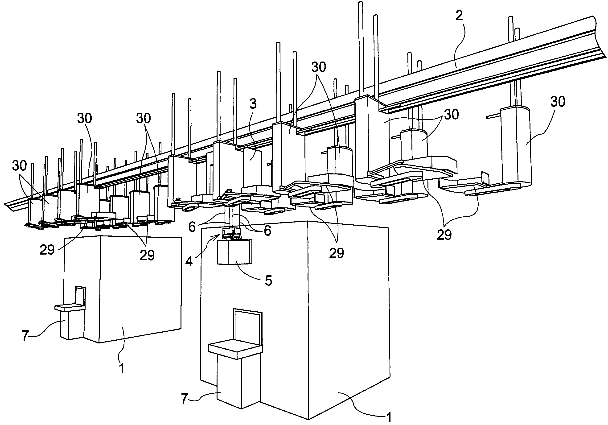
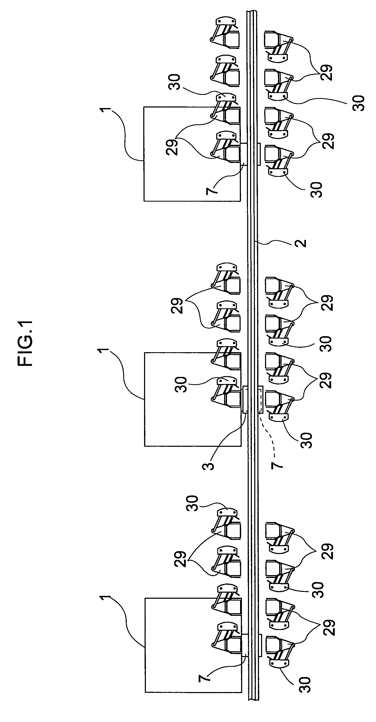
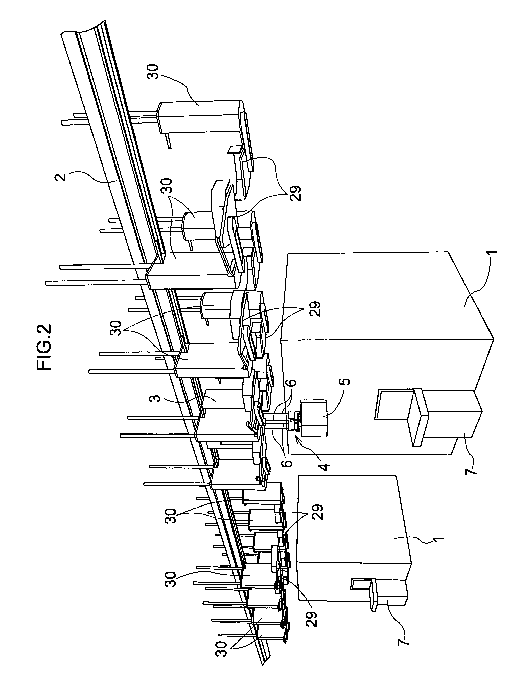
[0036]As shown in FIGS. 1 and 2, an article transport facility in the first embodiment includes a guide rail 2 installed as a moving path extending by way of a plurality of article processing units 1, and a transport vehicle 3 acting as a mobile body movable along the guide rail 2 for transporting articles. The articles herein are containers 5 storing semiconductor substrates, and the transport vehicle 3 transports the containers 5 between the plurality of article processing units 1. Each article processing units 1 performs a predetermined process for partly finished goods in the course of manufacturing semiconductor substrates, for example.
[0037]The transport vehicle 3 has a gripper 4 for vertically movably gripping a container 5 in a suspended state. The gripper 4 acts as a holder for holding a container 5.
[0038]As shown in FIG. 3, with the transport vehicle 3 standing still, the gripper 4 is vertically movable, by winding and unwinding wires 6, between an upper position adjacent ...
second embodiment
[0088]Next, an article transport facility in the second embodiment will be described. The second embodiment shows a modification of the support means in the first embodiment described above.
[0089]The construction of the support means in the second embodiment will be described hereinafter with reference to FIGS. 10 through 14. The other aspects of the construction are the same as in the first embodiment, and will not be described again.
[0090]FIG. 10 is a perspective view showing an overall construction of one article support 42. FIGS. 11 and 12 are perspective views of two article supports 42 arranged side by side, FIG. 11 shows both the article supports 42 located in an article storage position. FIG. 12 shows one of the article supports switched to an article transfer position. FIG. 13 (A) shows a plan view of an upper portion of the article support 42 located in the article storage position. FIG. 13 (B) shows a plan view of a lower portion of the article support 42 located in the a...
third embodiment
[0115]Next, an article transport facility in the third embodiment will be described. The third embodiment shows modifications of the fixed frame and slide guide mechanism in the second embodiment described above.
[0116]The constructions of fixed frame 74 and slide guide mechanism 70 in the third embodiment will be described hereinafter with reference to FIGS. 16 through 21. The other aspects of the construction will not be described again.
[0117]FIG. 16 is a perspective view showing four article supports 68 arranged side by side. FIG. 17 shows an exploded perspective view of an article support detached from the fixed frame 74. FIG. 18 shows a perspective view of an article support 68 located in an article storage position. FIG. 19 shows the article support 68 switched to an article transfer position. FIG. 20 shows a plan view of the article support 68 located in the article storage position. FIG. 21 shows a plan view of the article support 68 switched to the article transfer position....
PUM
 Abstract
Description
Claims
Application Information
 - R&D
- Intellectual Property
- Life Sciences
- Materials
- Tech Scout
- Unparalleled Data Quality
- Higher Quality Content
- 60% Fewer Hallucinations
Browse by: Latest US Patents, China's latest patents, Technical Efficacy Thesaurus, Application Domain, Technology Topic, Popular Technical Reports.
© 2025 PatSnap. All rights reserved.Legal|Privacy policy|Modern Slavery Act Transparency Statement|Sitemap|About US| Contact US: help@patsnap.com


