
Method and system for improving traffic safety

a technology for improving traffic safety and improving safety, applied in the field of methods and/or systems, can solve the problems of large number of accidents, driver distraction, and tiring driving, and achieve the effect of improving traffic safety

Active Publication Date: 2010-08-24
GM GLOBAL TECH OPERATIONS LLC
View PDF16 Cites 40 Cited by
  • Summary
  • Abstract
  • Description
  • Claims
  • Application Information

AI Technical Summary

Benefits of technology

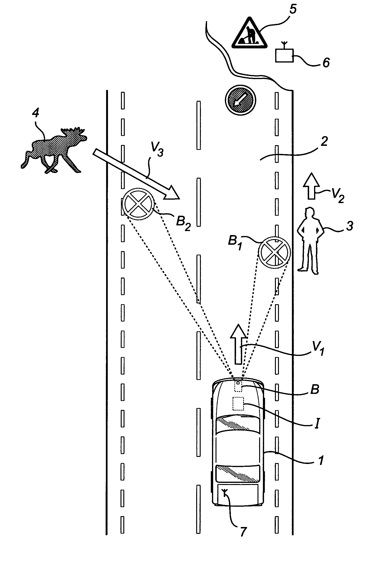
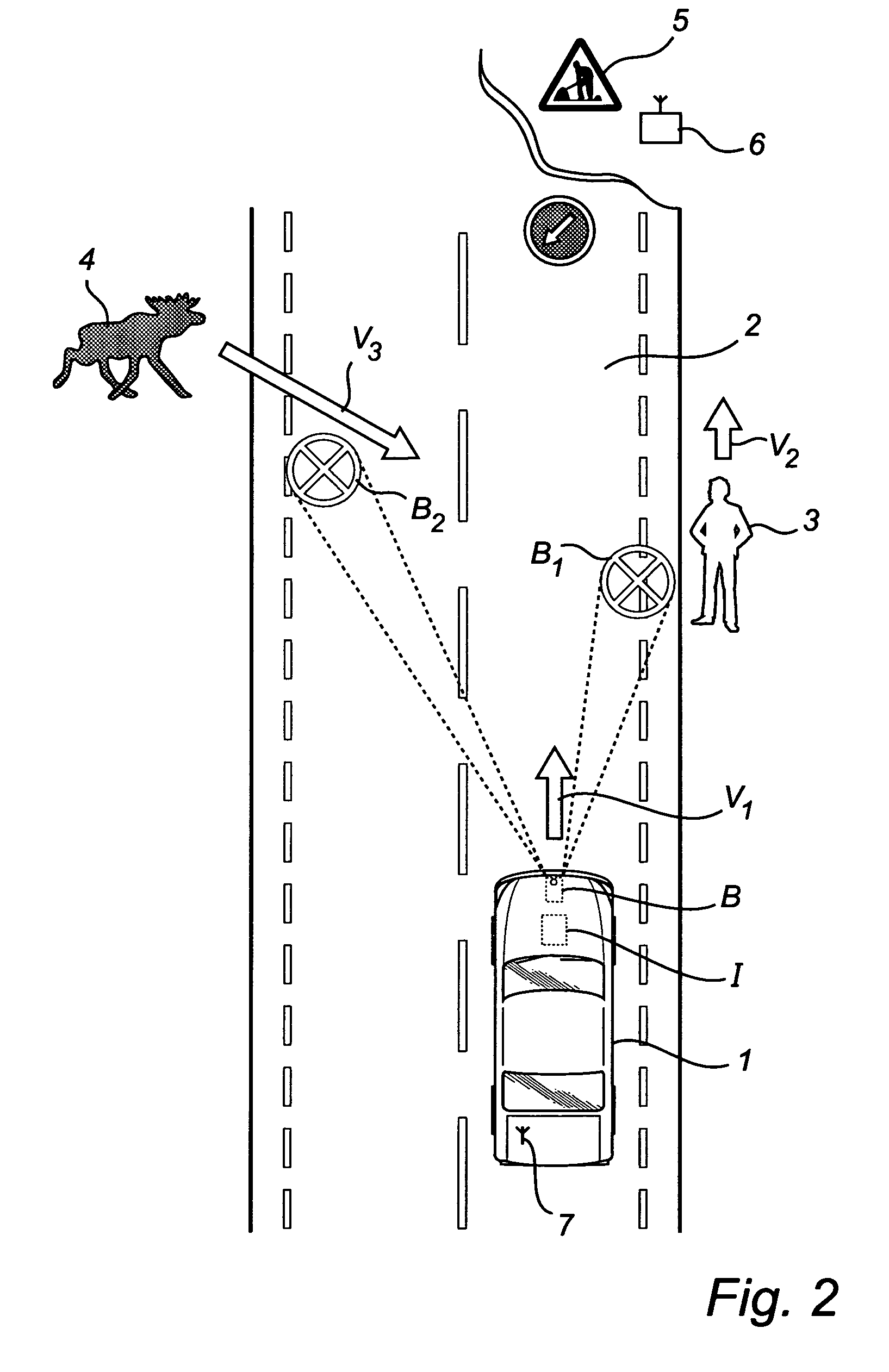
The present invention provides a method and system for improving traffic safety when driving a vehicle by detecting objects in the immediate surroundings of the vehicle and illuminating the roadway with a light pattern indicating the type of object that is relevant to the driving of the vehicle. This method helps to improve traffic safety by providing the driver with information about the objects approaching the vehicle without having to divert their attention from the roadway. The method can be used under various traffic and weather conditions, including dark, rain, snow, and fog. The system includes a camera, radar, or other device for retrieving data on the immediate surroundings of the vehicle, which can be used to create an image of the immediate surroundings of the vehicle. The illumination of the roadway is performed using at least one headlight and / or a laser light source, which can be adapted based on the traffic safety relevance index of the detected object. Overall, this invention provides a more effective and efficient way to improve traffic safety for drivers.

Problems solved by technology

A large number of these accidents occur when driving in the dark and under bad weather conditions.
Systems of the latter type which show important objects on a display mounted in the vehicle suffer from a serious drawback since they force the driver to divert his attention from the road, which results in the driver being distracted and makes driving tiring.
Moreover, the creation of a virtual image of the road on a display mounted in the vehicle makes the driver tend to rely on the image shown on the display, and not on the actual circumstances.
This system is both complicated and expensive and is not suitable for the current vehicle industry where cost is a crucial aspect.
However, the use of this system results, in the same way as mentioned above, in the attention of the driver of the vehicle being diverted from the road in order to locate the illuminated portions around the detected individual.

Method used


Image

  • Method and system for improving traffic safety
  • Method and system for improving traffic safety
  • Method and system for improving traffic safety

Examples


Embodiment Construction

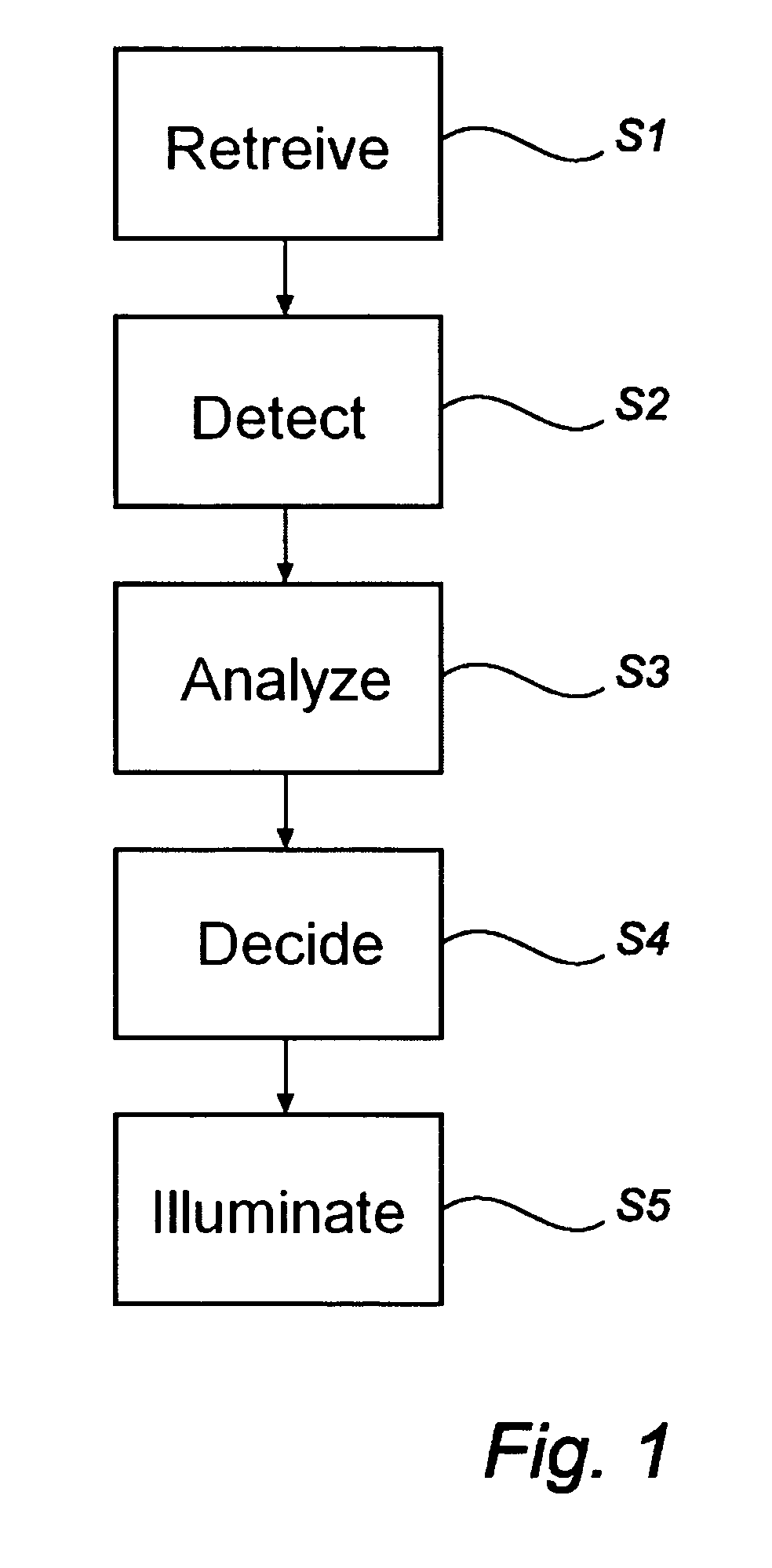
[0030]FIG. 1 is a flow chart describing a method according to an embodiment of the present invention for improving traffic safety. The flow chart shows the steps, S1 to S5, which are performed in an example embodiment of the present invention.

[0031]In step S1, data on the immediate surroundings of the vehicle is retrieved. This is done by retrieving data from for instance, one of, or a combination of, a camera, (for instance a thermal, CMOS and / or CCD camera) and / or radar equipment. The different types of cameras are suited to retrieve various types of information; for instance a thermal camera is suited to retrieve position and temperature information about an individual or an animal moving adjacent to the roadway. Radar equipment advantageously functions to assess, for instance, the distance to an adjacent object.

[0032]In an example embodiment, a camera and / or radar information are combined with position based navigation information. Position based navigation information preferabl...


PUM


Abstract

A method and system for improving traffic safety when driving a vehicle on a roadway including detecting at least one object in the immediate surroundings of the vehicle, analyzing the at least one detected object, deciding whether the at least one analyzed object is relevant in terms of traffic safety to the driving of the vehicle, and illuminating, via a light source, the roadway with a light pattern indicating the at least one object which is considered to be relevant in terms of traffic safety to the driving of the vehicle, thereby improving traffic safety.

Description

PRIORITY STATEMENT[0001]The present application hereby claims priority under 35 U.S.C. §119 on Swedish patent application No. SE 0501963-3 filed Sep. 6, 2005, the entire contents of which is hereby incorporated herein by reference.FIELD[0002]The invention generally relates to a method and / or a system for improving traffic safety when driving a vehicle on a roadway.BACKGROUND ART[0003]Vehicular traffic claims many victims every year. A large number of these accidents occur when driving in the dark and under bad weather conditions. Modern vehicles, such as for example cars, trucks and busses, are sometimes equipped with electronic systems which are adapted to support the driver when driving under unfavorable weather conditions. Some of these electronic systems are, for example, configured to adaptively direct or turn the headlights of the vehicle while taking a curve. Other systems are configured in such a manner that a display mounted in the vehicle shows objects that are considered ...

Claims


Application Information

Patent Timeline
Patent Type & Authority Patents(United States)
IPC IPC(8): B60Q1/26G06V10/145
CPCB60Q1/50B60Q2300/45B60Q2400/50G08G1/166G06V20/58G06V10/145B60Q1/085G08G1/16B60Q1/545B60Q1/52
Inventor WITTORF, MARTENHOFFMANN, LARS
Owner GM GLOBAL TECH OPERATIONS LLC
Learn More