
Multi-array sensor with integrated sub-array for parallax detection and photometer functionality

a multi-array sensor and parallax detection technology, applied in the field of multi-array sensor with parallax correction, can solve the problems of poor color imaging, limited image resolution, and handicaps of single-lens camera

Inactive Publication Date: 2010-08-24
APTINA IMAGING CORP
View PDF19 Cites 180 Cited by
  • Summary
  • Abstract
  • Description
  • Claims
  • Application Information

AI Technical Summary

Benefits of technology

"The present invention relates to methods and systems for imaging with parallax correction. The invention involves multiple lenses and imaging arrays that work together to capture images with improved resolution and color accuracy. The invention can be used in cameras to improve image quality and provide a better user experience. The technical effects of the invention include improved image resolution, improved color imaging, and improved parallax correction."

Problems solved by technology

The single-lens camera suffers from several handicaps, such as limited image resolution, poor color imaging, and improper luminance imaging.
Typically, image resolution limitations are a result of using a single sensor array containing a limited number of sensor elements.

Method used

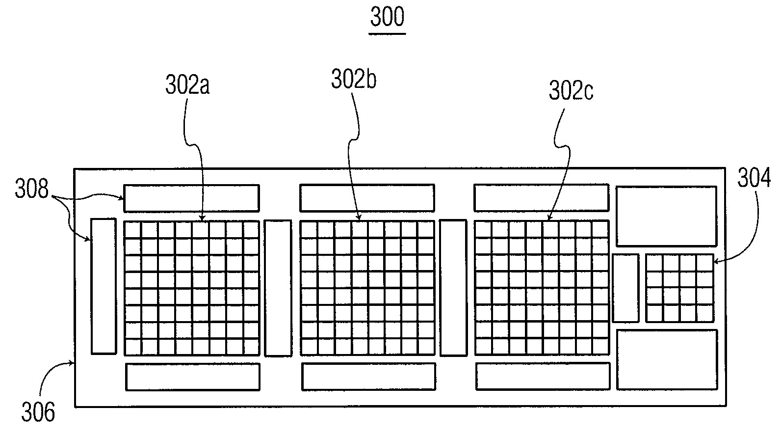
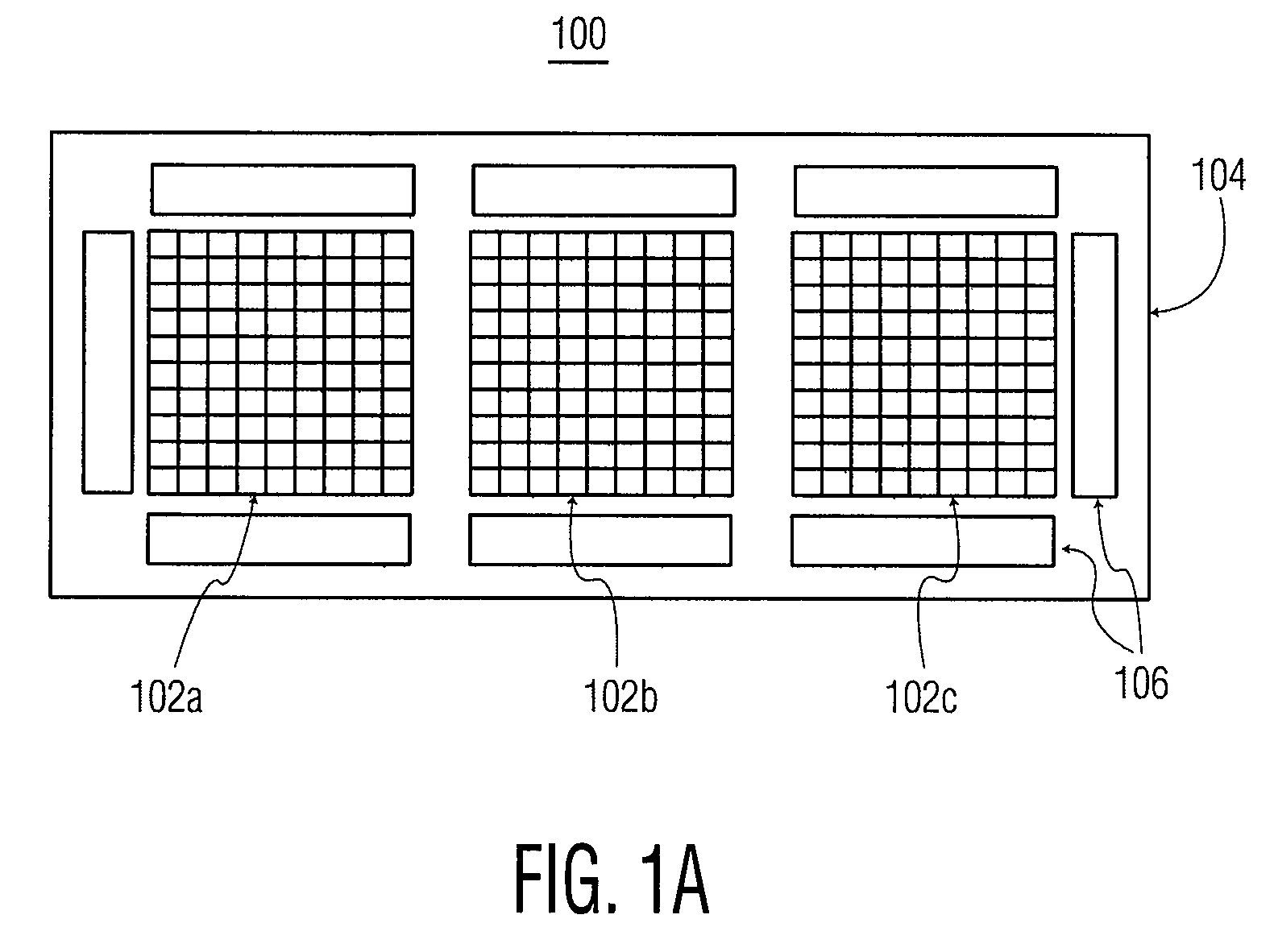
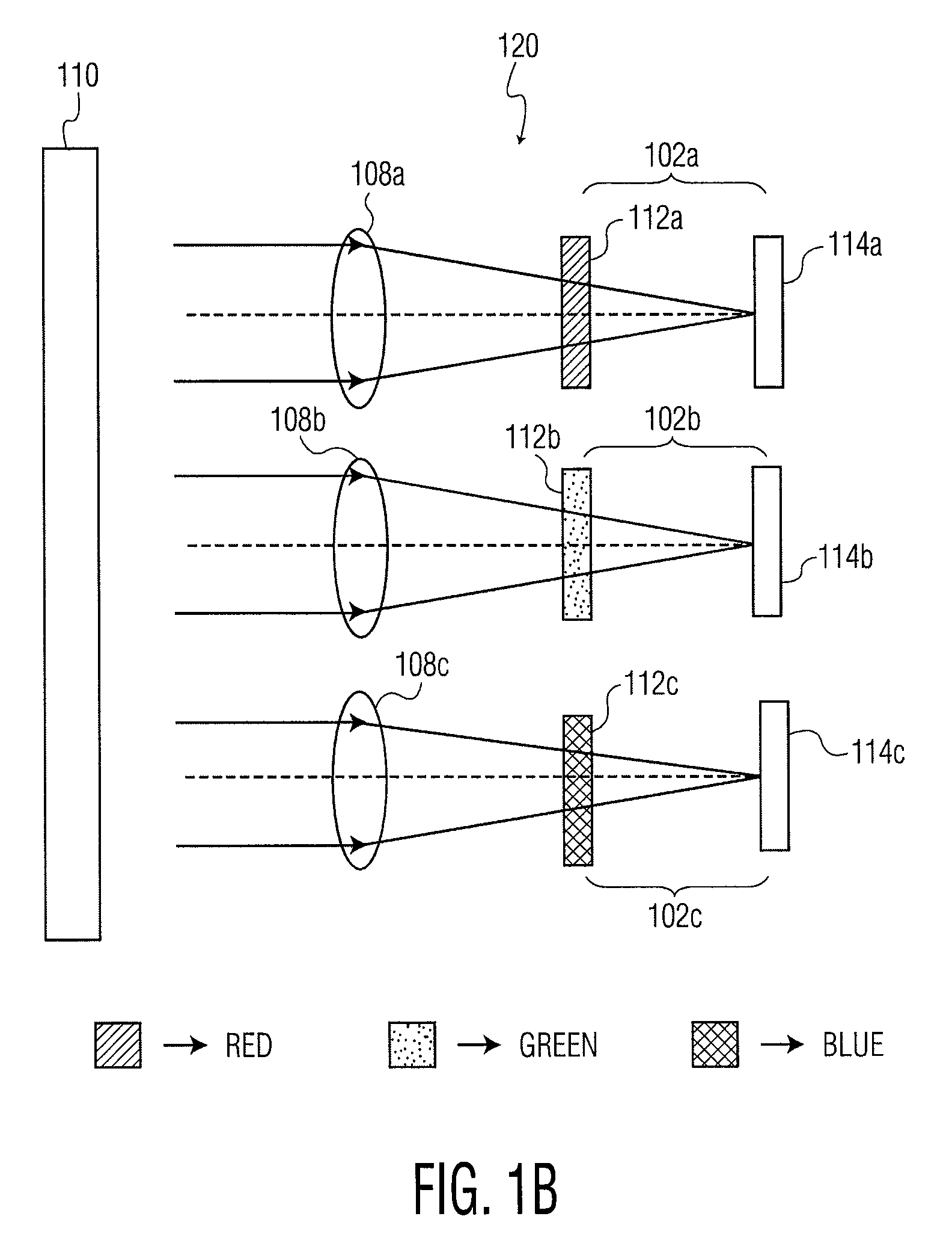

Image

  • Multi-array sensor with integrated sub-array for parallax detection and photometer functionality
  • Multi-array sensor with integrated sub-array for parallax detection and photometer functionality
  • Multi-array sensor with integrated sub-array for parallax detection and photometer functionality

Examples


Embodiment Construction

[0017]In the following detailed description, reference is made to the accompanied drawings which form a part hereof, and which illustrates specific embodiments of the present invention. These embodiments are described in sufficient detail to enable those of ordinary skill in the art to make and use the invention. It is also understood that structural, logical or procedural changes may be made to the specific embodiment disclosed without departing from the scope of the present invention.

[0018]The various embodiments generally describe systems and methods for imaging with parallax correction. The imaging systems generally incorporate multiple lenses that are individually configured to receive visible light from an object to be imaged and to direct this light upon a corresponding multiple imaging arrays. Chrominance and / or luminance information is then derived from signals generated in one or more of the imaging arrays.

[0019]It should be understood that, taken alone, an imaging array d...


PUM


Abstract

Methods and systems of imaging to correct parallax. Color information is received from multi-array sensors. Luminance information is received from a sub-array sensor arranged with the multi-array sensors. Color information received from at least one of the multi-array sensors is correlated with the luminance information received from the sub-array sensor. Color information is shifted among the multi-array sensors, based on the correlation, to correct the parallax.

Description

FIELD OF THE INVENTION[0001]The present invention relates to CMOS imagers and, more particularly, to methods and systems for multi array imaging with parallax correction.BACKGROUND OF THE INVENTION[0002]Image capture devices such as digital cameras, desktop cameras attached to personal computers, and cameras built into mobile telephones, typically have a single lens through which light that is received from an object to be photographed. The light is typically directed from the single lens onto a charge-coupled device (CCD) sensor array, or alternatively, a complementary metal oxide semiconductor (CMOS) sensor array. Because most of these cameras are color cameras, a pixilated color filter is interposed between the lens and the sensor array. The color filter normally contains an array of red, green, and blue filter elements. Each element of the color filter, regardless of the color transmitted through the element, is aligned with a sensor element located in the sensor array. Such an ...

Claims


Application Information

Patent Timeline
Patent Type & Authority Patents(United States)
IPC IPC(8): H04N5/225H04N7/14H04N23/12
CPCH04N5/2351H04N9/093H04N5/2353H04N2209/048H04N23/71H04N23/73H04N25/41H04N23/15
Inventor SMITH, SCOTT
Owner APTINA IMAGING CORP
Learn More