Insulated single beverage container cooler/holder

a beverage container and cooler technology, applied in the field of beverage coolers, can solve the problems of insulating but not providing any cooling to the beverage, insulating holders usually do not provide watertight sealing between the container and the holder, and insulators typically have seams that are not watertight, so as to facilitate the insertion of beverage containers

Inactive Publication Date: 2010-08-31
FARRELL EDWIN B
View PDF30 Cites 129 Cited by
  • Summary
  • Abstract
  • Description
  • Claims
  • Application Information

AI Technical Summary

Benefits of technology

[0014]The present invention is directed to an insulated beverage holder formed from neoprene or other insulating material. The holder includes a seal located at the upper opening of the housing. The seal can extend above the housing and can include an upper insertion portion and a lower sealing portion. The insertion portion helps ease the insertion of a beverage container into the holder and the sealing portion produces a watertight seal of the holder to the beverage container. An ice and water mixture can be placed into the holder prior to inserting the beverage container to provide cooling of the beverage while it is being consumed.

Problems solved by technology

The primary shortcoming of this design is that it only insulates but does not provide any cooling to the beverage.
Regardless of whether this bottom hole is used or not, these types of insulating holders usually do not provide watertight sealing between the container and holder.
In addition, the insulators typically have seams that are not watertight—particular where the bottom is attached to the cylindrical side.
On those without a hole in the bottom, they typically are not made to fit tightly on the container and thus can allow water to leak out between the container and holder.
Regardless of whether the holder is intended for use with cans or with bottles, the holders are do not typically provide for a space below the beverage container to accommodate a refrigerant.
However, this design suffers from several shortcomings including:(a) Expensive to manufacture—due to high tooling costs for injection molding and / or blow molding dies.(b) No way to “recharge” quickly—once the refrigerant in the device has warmed to the ambient external air temperate, there is no way to obtain continued cooling of the beverage or cooling of a new beverage without recharging the holder (i.e., make it cold again by putting it back in the freezer) or using another chilled holder.
This diminishes the usefulness and the convenience of the product since this type of product is often used outside, for example at a beach, where it is not possible to refreeze the product or, at least very least inconvenient to wait the several hours required to refreeze the refrigerant.
A sealing means between the holder and the beverage container permits the beverage container and the holder to be tipped for drinking without spilling the ice or ice and water used to provide the cooling.” The drawbacks of this design include:(a) Manufacturing Expense—The manufacturing costs of this design can be high due to high tooling costs for injection molding and / or blow molding dies.
The product also requires tooling for multiple parts and possibly expensive “overmolding” of parts used in the sealing means.(b) Limited range of beverage container diameters—due to materials used in sealing.
Testing has revealed that the product can leak when used in conjunction with certain national brand beverage bottles such as a “Sam Adams” brand beer bottle.(c) More expensive to print on.
However, it is believed that it is much less common that such vendors have the specialized equipment to print on the type of thermoplastic used for the IceTub™ holder.(d) Two piece construction.
In the event the seal, which is relatively small, is misplaced, lost or separated from the housing, the product will not work as intended.

Method used


Image

  • Insulated single beverage container cooler/holder
  • Insulated single beverage container cooler/holder
  • Insulated single beverage container cooler/holder

Examples


second embodiment

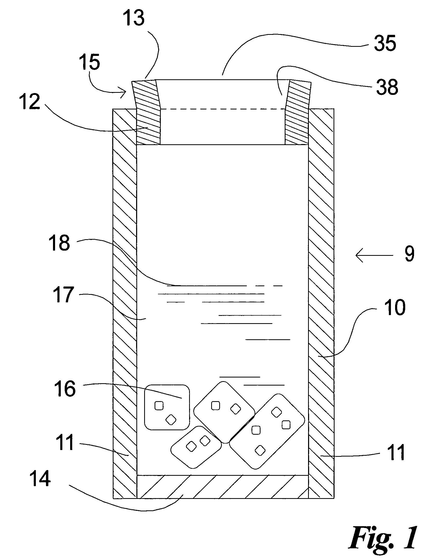
[0037]Referring now to FIGS. 5 and 6, a second embodiment 19 is shown in which the same seal 12 is concentrically positioned near the top opening of the housing 10 slightly below the top plane of housing 10. The remaining structural features of this second embodiment can be the same as that disclosed above in connection with FIGS. 1-4. As in that first embodiment, the overall dimensions (width, inside diameter, outside diameter and thickness) of the seal 12 impact the water tightness of the seal. These dimensional aspects will be further described farther below. For this embodiment, the outside diameter of the seal 12 should be equal to or slightly greater than the inside diameter of the housing. The seal should be sufficiently thick (e.g., ¼″ to ⅜″) and it should have an inside diameter slightly smaller than the outside diameter of the beverage container 22 such that the compression of the seal 12 against the container results in a watertight seal. This prevents the ice and water m...

third embodiment

[0038]The remaining embodiments each utilize certain components in common with the first embodiment of FIGS. 1-4 and like elements utilize the same reference numerals except being offset by 100, 200, etc.

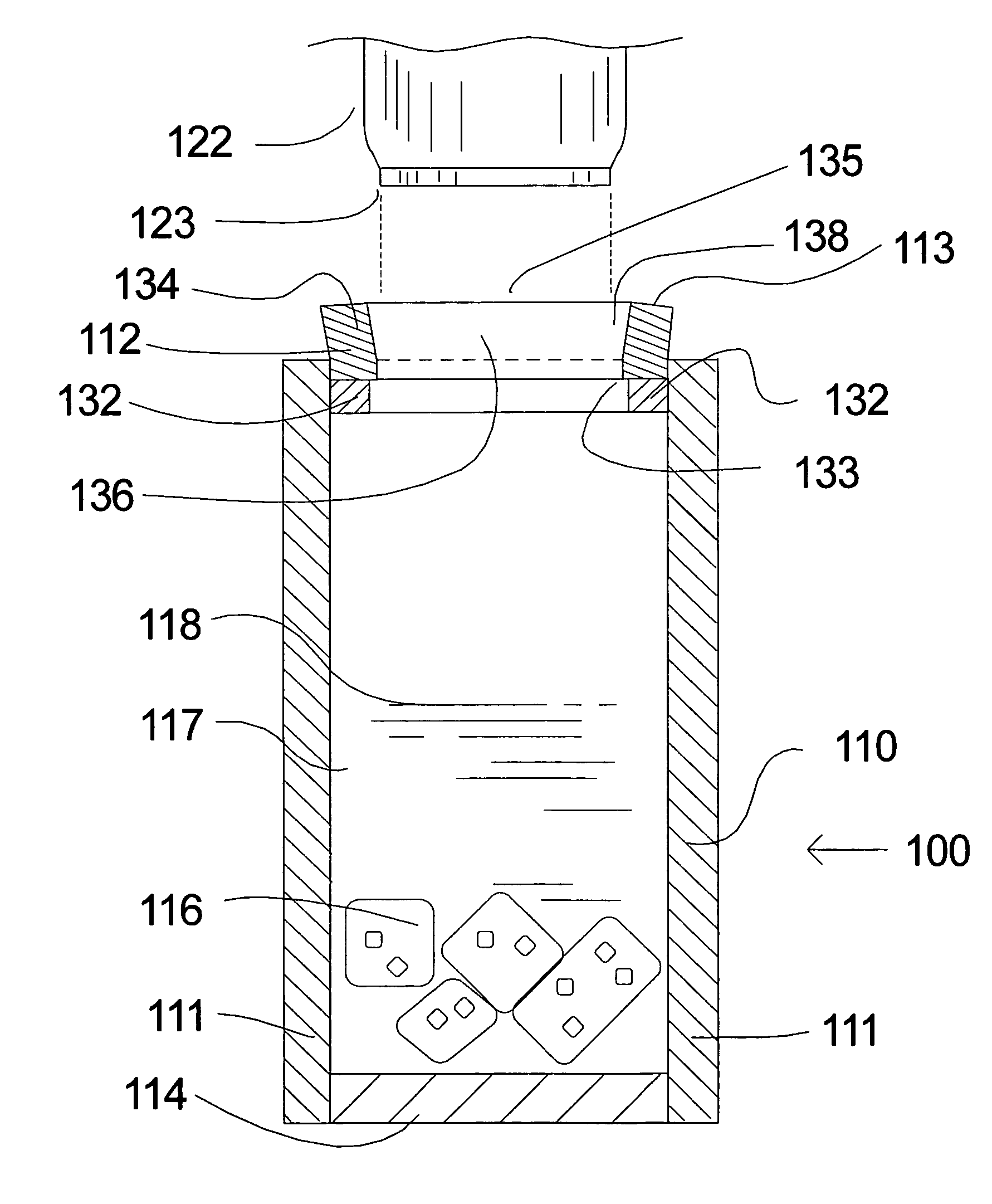
[0039]Turning now to FIGS. 7-10, there is shown a third embodiment 100 in which the seal 112 comprises a two-part seal having a lower sealing portion 132 and an upper insertion portion 134. In this embodiment, the sealing portion 132 and insertion portion 134 are separate components secured directly together and / or each to the sleeve 111 in close abutting contact with each other.

[0040]The insertion portion 134 is in the shape of a wide ring sized to fit within the housing while extending above the opening of the housing. It is constructed of a stretchable / elastic, resiliently compressible and flexible closed cell foam rubber material and its characteristics impact the effectiveness of the insertion portion 134. For both the seal 12 of the first two embodiments and the insertion port...

fourth embodiment

[0070]Referring now to FIG. 11, a fourth embodiment 200 is shown. The seal 412 used in this embodiment comprises a one-piece seal formed from an insertion portion 244 that is unitary with the lower, sealing portion 242. This construction is similar to that of the third embodiment, except that in the third embodiment, the radially inward surface of the insertion portion 134 was nylon laminated neoprene and the sealing portion 132 was unlaminated neoprene, whereas in this embodiment 200, the radially inward facing side 248 of insertion portion 244 (above the imaginary line 247) does not have a nylon fabric laminate but is smooth neoprene unlaminated to improve the watertight seal of seal 212. Thus, the entire inner surface of the seal 212 (both the sealing portion 242 and insertion portion 244) is unlaminated neoprene.


PUM


Abstract

An insulated beverage holder formed from neoprene and including a seal located at the upper opening of the housing. The seal can extend above the housing and can include an upper insertion portion and a lower sealing portion. The insertion portion helps ease the insertion of a beverage container into the holder and the sealing portion produces a watertight seal of the holder to the beverage container. An ice and water mixture can be placed into the holder prior to inserting the beverage container to provide cooling of the beverage while it is being consumed.

Description

CROSS-REFERENCE TO RELATED APPLICATION[0001]This application claims the priority of U.S. Provisional Application No. 60 / 606,393, filed Sep. 1, 2004, the entire contents of which are hereby incorporated by reference.TECHNICAL FIELD[0002]This invention relates generally to holders for beverage containers such as bottles and cans, and more particularly to cooling and insulating beverage holders designed to either chill a beverage or reduce temperature changes of a beverage in the beverage container.BACKGROUND OF THE INVENTION[0003]The majority of beverage container holders have been designed for either 12 oz cans or 12 oz bottles. Recently, the popularity of water bottles has created a market for bottle holders that can fit 16-25 oz and greater water bottles. The term beverage container is not limited to the typical twelve ounce bottle or can and may include water bottles, soda bottles, plastic squeeze bottles and even plastic cups or glass drinkware. The use of a cup or glass is usefu...

Claims


Application Information

Patent Timeline
Patent Type & Authority Patents(United States)
IPC IPC(8): A47F5/00B65D25/00
CPCB65D81/3879F25D2331/805
Inventor FARRELL, EDWIN B.
Owner FARRELL EDWIN B
Why Eureka
Try Eureka