
Electrical connector having an improved magnetic module

a technology of magnetic module and electric connector, which is applied in the direction of coupling device connection, fixed transformer, coupling protective earth/shielding arrangement, etc., can solve the problems of increasing the cost of manufacture and complicated assembly of toroidal coil pair

Inactive Publication Date: 2010-08-31
HON HAI PRECISION IND CO LTD
View PDF44 Cites 25 Cited by
  • Summary
  • Abstract
  • Description
  • Claims
  • Application Information

AI Technical Summary

Benefits of technology

[0007]An object of the present invention is to provide an electrical connector having a magnetic module which comprises a toroidal coil pair having a pair of toroidal bodies electrically connected with each other efficiently.
[0009]Advantages of the present invention are to provide a toroidal coil pair having a first toroidal body and a second toroidal body respectively mounted to a printed circuit board automatically and connected with each other by a circuit provided on the printed circuit board. Therefore, it is efficient to electrically connect the first toroidal body to the second toroidal body by a circuit of the printed circuit board and reduce the cost of manufacture.

Problems solved by technology

It would result in complicating the assembly of the toroidal coil pair and increasing the cost of manufacture.

Method used


Image

  • Electrical connector having an improved magnetic module
  • Electrical connector having an improved magnetic module
  • Electrical connector having an improved magnetic module

Examples


Embodiment Construction

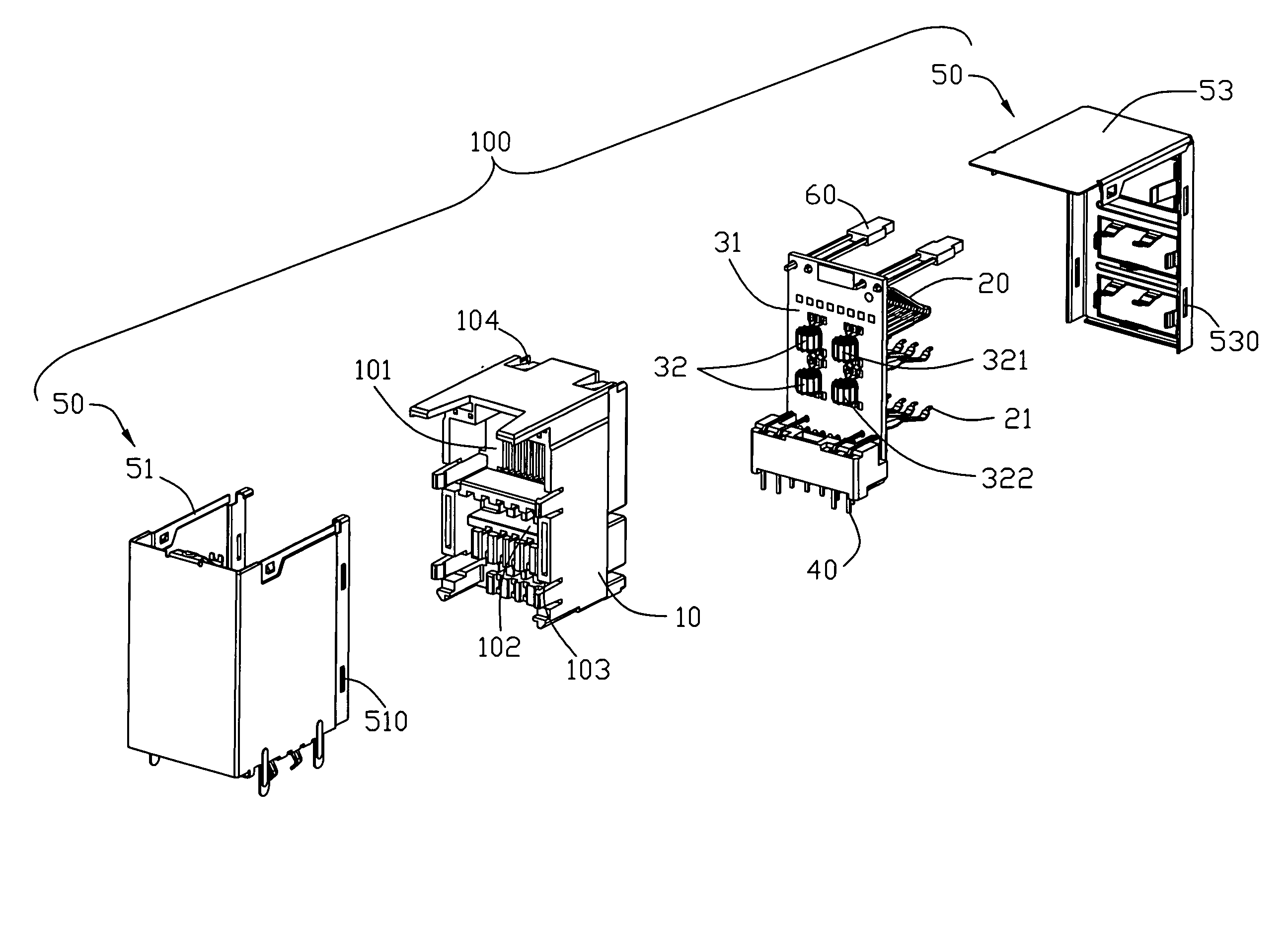
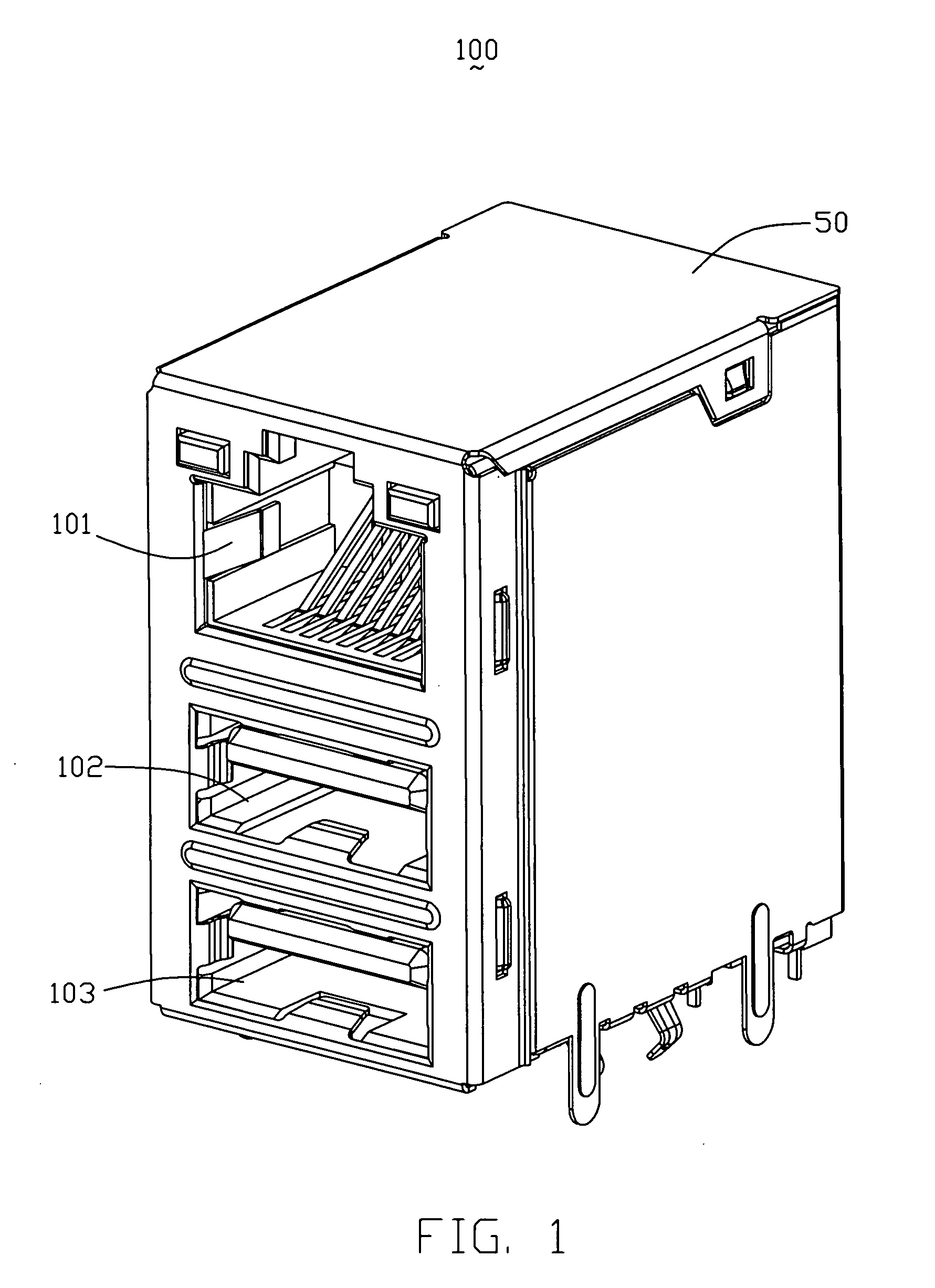
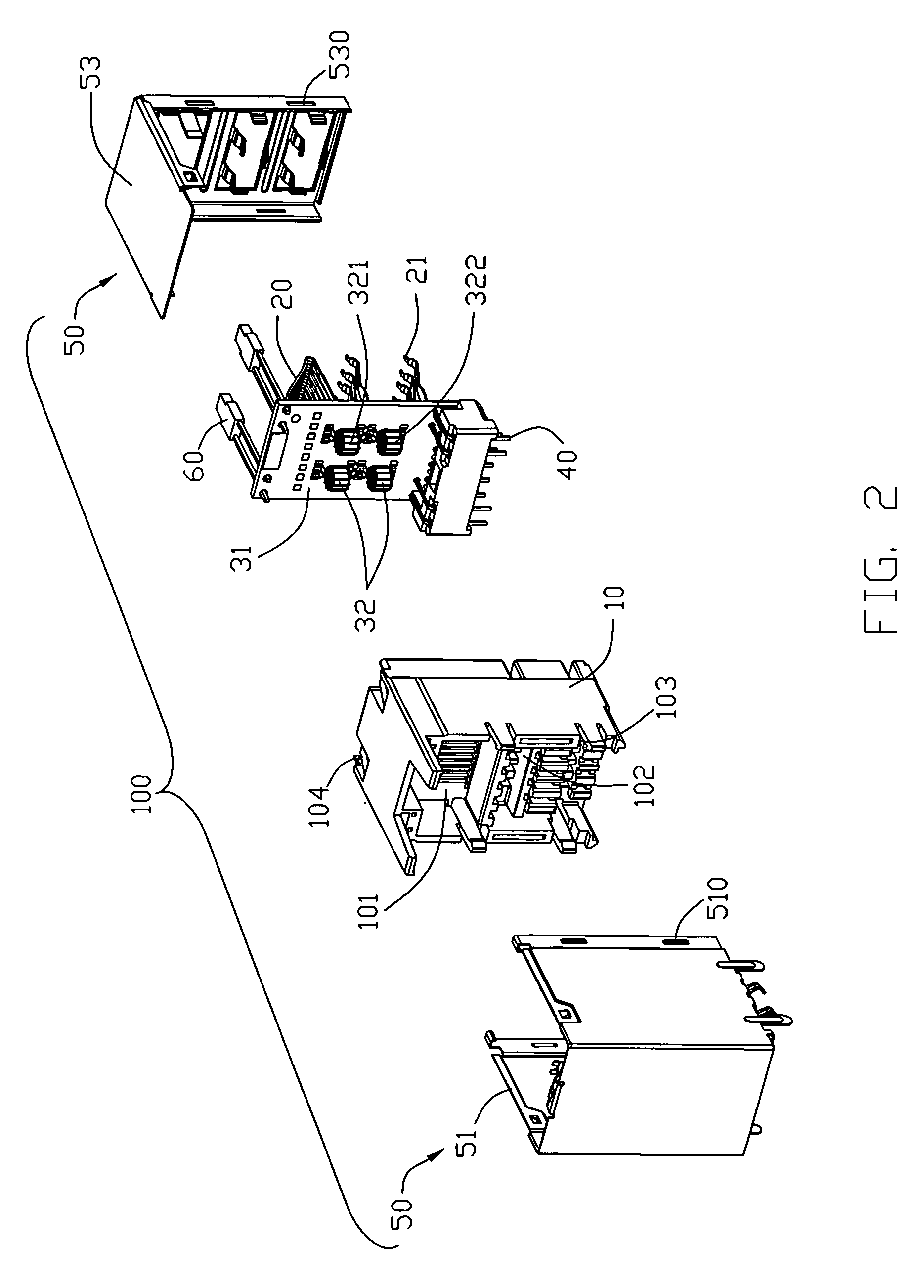
[0017]Reference will now be made to the drawing figures to describe the present invention in detail. Referring to FIGS. 1-3, an electrical connector 100 is commonly used in the computer or network appliance as input / output port for transmitting data or signals. The electrical connector 100 includes a housing 10 defining an opening 101 therein, a magnetic module 30 having a printed circuit board 31, and a shield 50 surrounding the housing 10.

[0018]The electrical connector 100 has a first set of terminals 20 mounted to a front face of the printed circuit board 31 and received into the opening 101, a second set of terminals 40 mounted to a rear side of the printed circuit board 31 and extending downwardly for connecting with a mother printed circuit board (not shown), and two groups of pins 21 assembled to the printed circuit board 31 and paralleled to the first set of terminals 20. The electrical connector 100 further comprises a pair of LEDs 60 (Light Emitting Diodes) retained in cor...


PUM


Abstract

An electrical connector (100) has a housing (10) defining an opening therein (101), a magnetic module (3) mounted to the housing and a shield (50) surrounding the housing. The magnetic module includes a printed circuit board (31), a first set of terminals (20) mounted to a front face of the printed circuit board and received in the opening, a second set of terminals (21) mounted to a rear side of the printed circuit board, a toroidal coil pair (32) mounted to the printed circuit board and having a first toroidal body and (321), and a second toroidal body (322) electrically connected with each other by a circuit provided on the printed circuit board.

Description

BACKGROUND OF THE INVENTION[0001]1. Field of the Invention[0002]The present invention relates to an electrical connector, and particularly to an electrical connector having an improved magnetic module.[0003]2. Description of Prior Arts[0004]U.S. Pat. No. 5,736,910 issued on Apr. 7, 1998 discloses a modular jack mounted onto a mother printed circuit board and adapted for receiving a plug. The modular jack includes a housing defining a receptacle, a daughter printed circuit board attached to a rear portion of the housing, a first set of contacts mounted to the housing for engaging with the plug and a second set of contacts assembled to the printed circuit board for connecting to the mother printed circuit board. A plurality of toroidal coil pairs are interposed between the first contacts and the second contacts for eliminating high frequency noise. Each toroidal coil pair has a first toroidal body functioning as a common mode filter, a second toroidal body functioning as a transformer...

Claims


Application Information

Patent Timeline
Patent Type & Authority Patents(United States)
IPC IPC(8): H01R3/00
CPCH01R13/719H01R13/659H01F30/16H01F2027/065H01R13/6633H01R13/7175H01R13/6461H01R24/62H01R27/02
Inventor WU, LI-CHUN
Owner HON HAI PRECISION IND CO LTD
Learn More