Microelectromechanical inertial sensor, in particular for free-fall detection applications

a micro-electromechanical and sensor technology, applied in the direction of acceleration measurement in multiple dimensions, acceleration measurement using interia forces, mechanical means for characerising devices, etc., can solve the problems of permanent damage and consequent loss of stored data, portable apparatuses are very liable to violent impact, and hard disks may suffer damage when used in portable applications

Active Publication Date: 2010-09-14
STMICROELECTRONICS SRL
View PDF7 Cites 33 Cited by
  • Summary
  • Abstract
  • Description
  • Claims
  • Application Information

AI Technical Summary

Benefits of technology

[0011]One embodiment of the present invention provides a microelectromechanical inertial sensor, in particular an accelerometer, and a corresponding free-fall detection device which enables the aforesaid disadvantages to be overcome and is an improvement of known devices.

Problems solved by technology

However, hard disks may suffer damage when used in portable applications.
In fact, portable apparatuses are very liable to violent impact, in particular when they fall to the ground during their normal use.
The impact of the portable apparatus against the ground has harmful repercussions on the hard disk inside it, producing in the worst case permanent damage and consequent loss of the stored data.
Hard disks are particularly susceptible to impact, in so far as a read / write head is normally kept at a small distance from a corresponding data-storage medium.
Consequently, due to the impact, the read / write head hits the storage medium and can get damaged together with it.
In particular, the displacement of the mobile mass occurs also in the presence of a static acceleration (for example, the acceleration of gravity), generating a corresponding capacitive unbalancing, which is detected by the interface electronics.
The operations described (in particular the calculation of the vector sum of the individual components of acceleration) are rather laborious to carry out and render the free-fall detection circuit complex.

Method used


Image

  • Microelectromechanical inertial sensor, in particular for free-fall detection applications
  • Microelectromechanical inertial sensor, in particular for free-fall detection applications
  • Microelectromechanical inertial sensor, in particular for free-fall detection applications

Examples


second embodiment

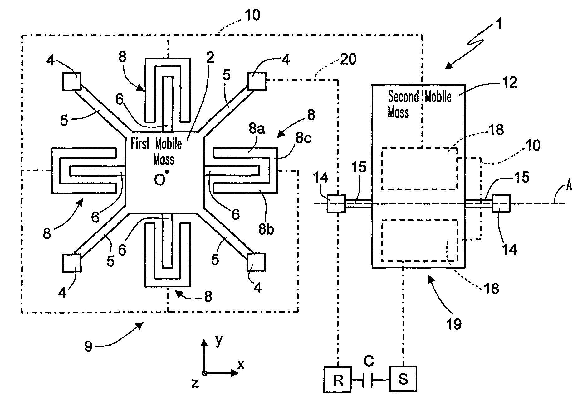
[0033]FIG. 2 shows the inertial sensor 1, which is advantageous in that it enables a reduction of a corresponding area occupation.

[0034]In detail, unlike what has been described previously, the first mobile mass 2 is hollow, frame shaped, and defines inside it a window 21. The second mobile mass 12 is housed inside the window 21, and the second elastic elements 15 are fixed to internal sides of the frame (in this case the second anchorages 14, as likewise the second electrical interconnections 20, are not present). The remaining part of the detection structure is not modified, and in particular the configuration and arrangement of the mobile electrodes 6 and of the first and second fixed electrodes 8, 18, as likewise their interconnections, which enable automatic detection of the vector sum of the components of acceleration ax, ay and az, is not changed.

third embodiment

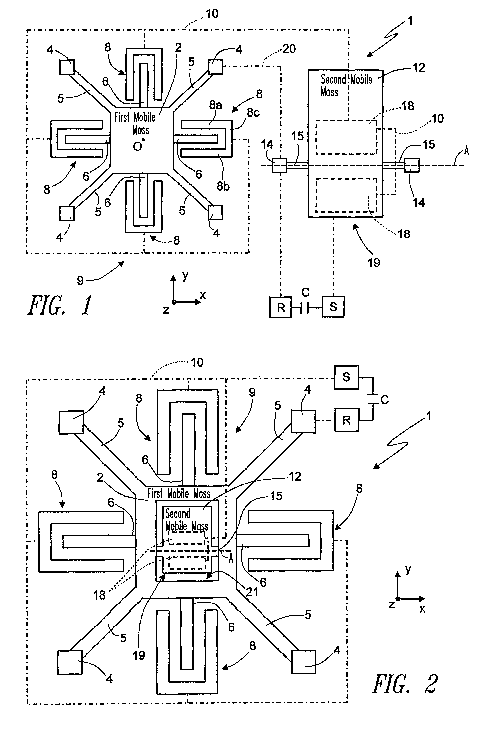
[0035]the inertial sensor 1 envisages a different configuration of the first detection structure 9 sensitive to accelerations in the plane xy, in particular substantially similar to what is described in US Publication No. 2005 / 0274184 A1 filed on Sep. 23, 2004 in the name of the present applicant, relating to a planar inertial sensor.

[0036]In detail (FIG. 3), the first mobile mass 2 has in plan view a circular shape and is connected to the substrate by means of just one first anchorage 4, set centrally. The first mobile mass 2 has a central hole 22 delimiting an internal circumference thereof. The first anchorage 4 extends inside the central hole 22 and is connected to the internal circumference by the first elastic elements 5, which have in this case the shape of an isotropic spiral, having a reduced width so as to enable displacements of the first mobile mass 2 in any planar direction. The mobile electrodes 6 are formed by a plurality of rings 24, concentric with respect to one an...

first embodiment

[0037]The second detection structure 19 is not modified with respect to the In particular, the first electrical interconnections 10 connect the various arched portions 26 to one another (in a way not illustrated) and to the second fixed electrodes 18, while the second electrical interconnections 20 connect the first and second anchorages 4, 14.

[0038]As described in detail in the aforesaid document, the first mobile mass 2 is sensitive to accelerations acting along any direction of the plane xy, and, as it moves in this direction, the distance of separation between the rings 24 and the arched portions 26 varies. The capacitive variation is also in this case increasing and directly proportional to the acceleration acting on the inertial sensor in any direction lying in the plane xy (in this case, consequently, only one capacitor for detection of accelerations in the plane xy is present, in so far as the sensor does not detect in this case the components of acceleration, but directly ...


PUM


Abstract

An inertial sensor provided with a detection structure sensitive to a first, a second and a third component of acceleration along respective directions of detection, and generating respective electrical quantities as a function of said components of acceleration. The detection structure supplies at output a resultant electrical quantity obtained as combination of said electrical quantities, and correlated to the value of a resultant acceleration acting on the inertial sensor, given by a vector sum of the components of acceleration. In particular, the detection structure is of a microelectromechanical type, and comprises a mobile portion made of semiconductor material forming with a fixed portion a first, a second and a third detection capacitor, and an electrical-interconnection portion, connecting the detection capacitors in parallel; the resultant electrical quantity being the capacitance obtained from said connection in parallel.

Description

BACKGROUND OF THE INVENTION[0001]1. Field of the Invention[0002]The present invention relates to a microelectromechanical inertial sensor, in particular for free-fall detection applications, to which the following treatment will make explicit reference without this implying any loss in generality.[0003]2. Description of the Related Art[0004]As is known, there is an increasingly widespread use, in portable devices, such as for example laptops, PDAs (Personal Data Assistants), digital audio players, cell phones, digital camcorders, portable computers and the like, of hard-disk (HD) units for storage of data. In fact, hard disks have a high storage capacity, a high access speed, and a low cost.[0005]However, hard disks may suffer damage when used in portable applications. In fact, portable apparatuses are very liable to violent impact, in particular when they fall to the ground during their normal use. The impact of the portable apparatus against the ground has harmful repercussions on...

Claims


Application Information

Patent Timeline
Patent Type & Authority Patents(United States)
IPC IPC(8): G01P15/08G01P15/18
CPCG01P15/0891G01P15/125G01P15/18G11B19/04G01P2015/082
Inventor MERASSI, ANGELOZERBINI, SARAHLASALANDRA, ERNESTOVIGNA, BENEDETTO
Owner STMICROELECTRONICS SRL
Why Eureka
Try Eureka