Coupling device for a fluid line

a fluid line and coupling device technology, applied in the direction of fluid pressure sealing joints, joints with sealing surfaces, sleeve/socket joints, etc., can solve the problems of inconvenient handling and inability to ensure a proper engagement, and achieve the effect of relatively easy operation

Inactive Publication Date: 2010-09-14
FESTO AG & CO KG
View PDF19 Cites 9 Cited by
  • Summary
  • Abstract
  • Description
  • Claims
  • Application Information

AI Technical Summary

Benefits of technology

[0007]One object of the present invention is to design a coupling device which may be operated relatively easily even in the case of a relatively large number of gripping teeth.
[0013]Each gripping tooth may be provided with its own actuating portion individually. This ensures mutually independent activation of the gripping teeth and avoids interference between the teeth.
[0015]Owing to the actuating portions running in the guide grooves it is possible furthermore for a means preventing rotation of the actuating sleeve to be provided.
[0019]In order to produce axially spaced apart gripping teeth at least two suitably spaced gripping teeth are preferably provided on at least some and more particularly all support arms. In this respect it is an advantage, if the gripping teeth arranged of the same support arm are offset in relation to one another in the peripheral direction of the collet. The latter feature ensures an even distribution of the points of engagement between the gripping teeth and the fluid line along the outer periphery of the latter.

Problems solved by technology

In order to ensure that the gripping teeth may take a proper hold on the fluid line, in this case the collet must be shifted applying a relative heavy force and this makes handling inconvenient.
A disadvantage of this coupling device is inter alia also that owing to lack of any active actuation of the gripping teeth it is not always possible to ensure a proper engagement with the inserted select, if its outer dimensions are subject to substantial manufacturing errors.

Method used


Image

  • Coupling device for a fluid line
  • Coupling device for a fluid line
  • Coupling device for a fluid line

Examples


Embodiment Construction

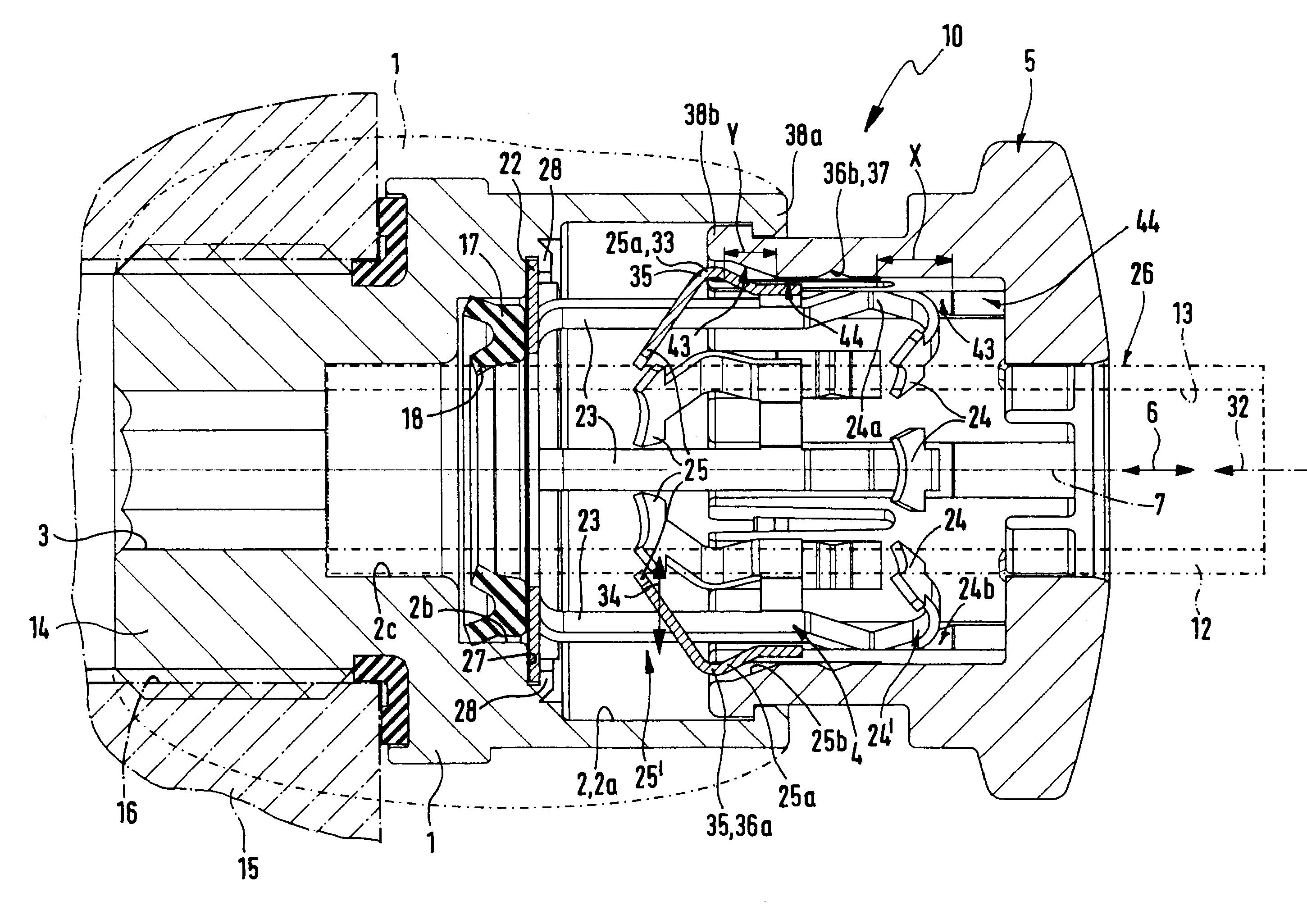
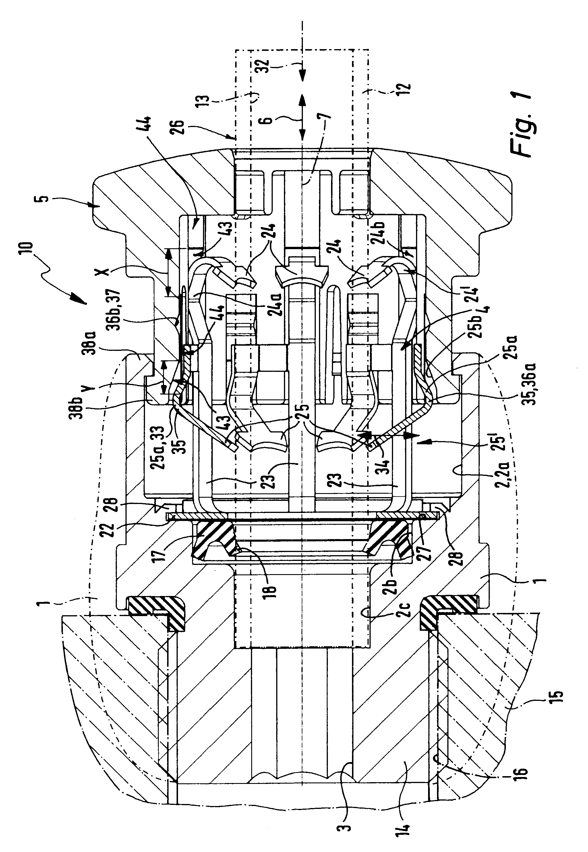
[0035]The coupling device generally referenced 10 comprises a main body 1 in which a socket 2 opening at an outer face and preferably with a circular cross section is formed which preferably coaxially is adjoined by a fluid line 3 extending in the main body 1. In the socket 2 a collet 4 with a sleeve-like configuration us placed and at least a part of its length is coaxially received in the socket. An actuating sleeve 5, which is coaxial in relation to the collet 4, encircles the collet 4 and in relation to the same and to the main body 1 is able to be shifted with a movement 6 indicated by a double arrow. The displacement direction extends axially, i.e., in the direction of the common longitudinal axis 7 of the socket 2, of the collet 4 and of the actuating sleeve 5.

[0036]A fluid line 12, indicated in chained lines, is introduced into the socket 2 through the actuating sleeve 5 and the collet 4 and it may be restrained in the inserted state by the collet 4. The fluid duct 13 formed...


PUM


Abstract

A coupling device for a fluid line has a collet and an axially movable actuating sleeve serving for operation of the collet. The collet bears several gripping teeth with associated actuating portions able to be acted on by actuating faces on the actuating sleeve in order to hold the inserted fluid line. In the non-operated state of the actuating sleeve there are at least partly different distances between the mutually associated actuating portions and actuating faces so that on actuation of the actuating sleeve several actuating portions of the collet are acted on one after the other. This means that the necessary actuating force is reduced.

Description

FIELD OF THE INVENTION[0001]The invention relates to a coupling device for a fluid line comprising a sleeve-like collet bearing against a main body axially and into which a fluid line to be coupled may be coaxially inserted and which has a plurality of axially extending support arms distributed in the peripheral direction and each bearing at least one radially inwardly extending gripping tooth, a plurality of gripping teeth being associated with different actuating portions provided on the collet such portions being able to be actuated by axial displacement of an actuating sleeve arranged around the collet by actuating faces disposed on the sleeve in order to thrust the gripping teeth radially inward to perform a clamping operation radially inwardly and clamp same against the outer periphery of the inserted fluid line.BACKGROUND OF THE INVENTION[0002]A coupling device disclosed in the European patent publication EP 1038138 B1 of this type comprises a sleeve-like collet with a meande...

Claims


Application Information

Patent Timeline
Patent Type & Authority Patents(United States)
IPC IPC(8): F16L21/06
CPCF16L33/222F16L37/091F16L37/0915F16L37/08
Inventor KEES, ULRICHROHRIG, HARALD
Owner FESTO AG & CO KG
Why Eureka
Try Eureka