RF connector with integrated shield

a technology of shielding and connectors, applied in the direction of coupling device connections, coupling protective earth/shielding arrangements, electric discharge lamps, etc., can solve problems such as leakage problems in many terminal connectors

Active Publication Date: 2010-09-14
APTIV TECH LTD
View PDF9 Cites 27 Cited by
  • Summary
  • Abstract
  • Description
  • Claims
  • Application Information

AI Technical Summary

Benefits of technology

[0008]The shield in one embodiment has an axially extending seam. In another embodiment, the seam is provided with overlapping tabs extending along the length of the shield. In another embodiment, the seam is provided with complementary interlocking tabs and notches to prevent the seam from opening up. In accordance with another aspect of the invention, a tubular shield for an RF terminal connector assembly has a set of resilient radially inwardly extending contact fingers at each end for connection to respective connecting ends of complementary terminals for first and second coaxial cables.

Problems solved by technology

New desired frequencies of 3 or 4 GHz create leakage issues for many terminal connectors.
Furthermore, present day connectors need to be properly seated to provide adequate shielding i.e. improper station causes significant RF leakage.

Method used


Image

  • RF connector with integrated shield
  • RF connector with integrated shield
  • RF connector with integrated shield

Examples


Embodiment Construction

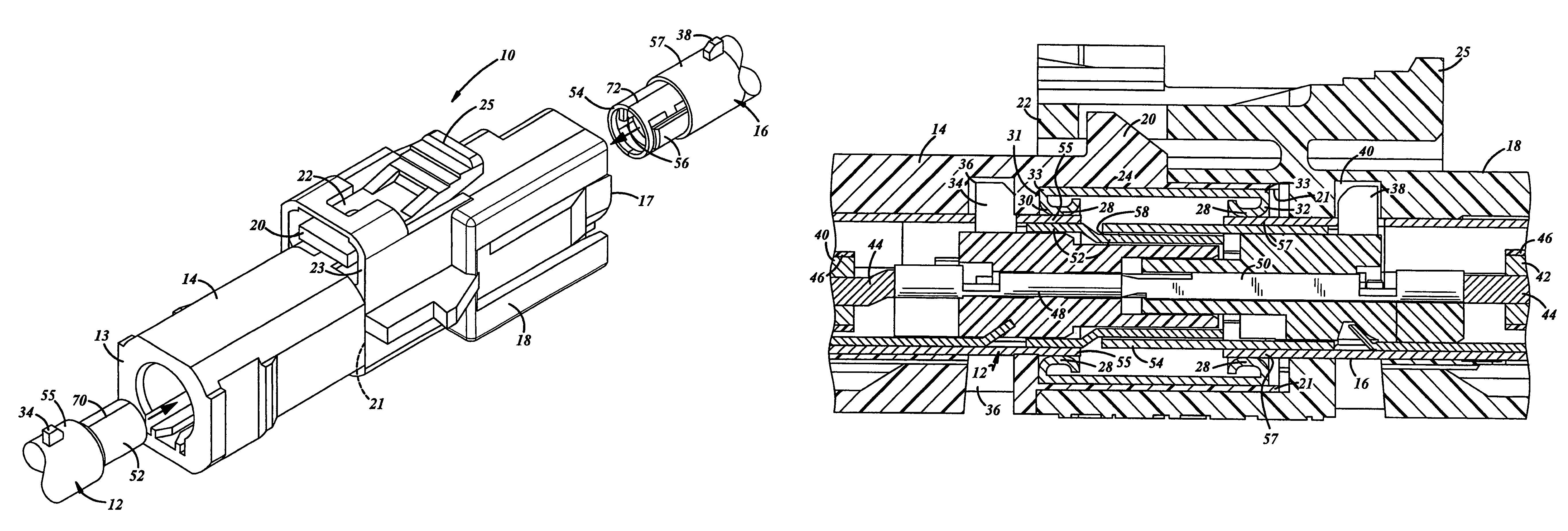
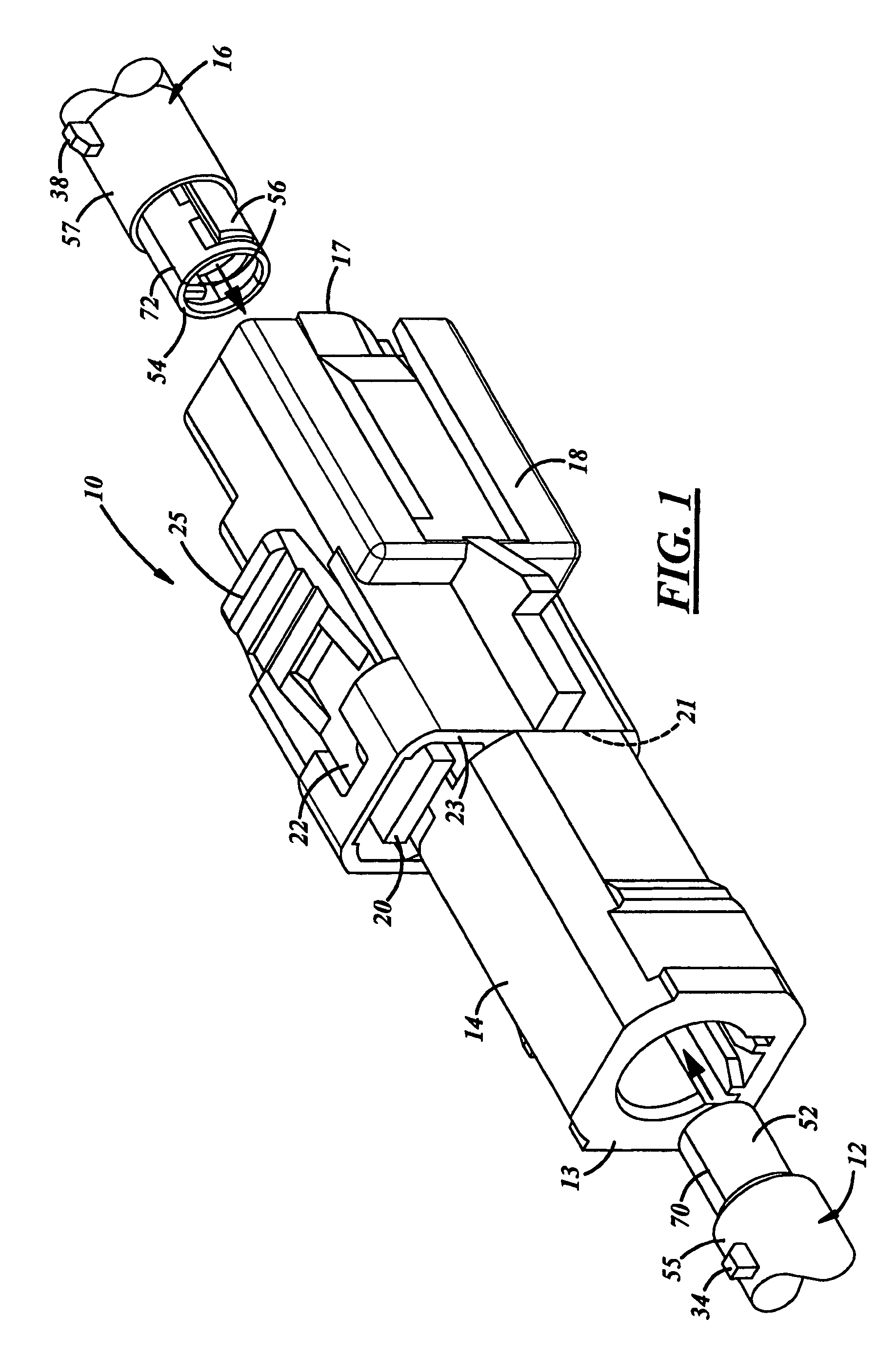
[0017]Referring now to FIG. 1, an RF connection 10 has a male terminal assembly 12 connected through one end 13 of a male plastic housing 14. A female terminal assembly 16 is connected through one end 17 of a female plastic housing 18. The male and female plastic housings 14 and 18 are constructed to releasable snap fit together at their respective second ends 21 and 23 with a tab 20, release latch 22 and operation latch handle 25 on the respective male and female housings 14 and 18.

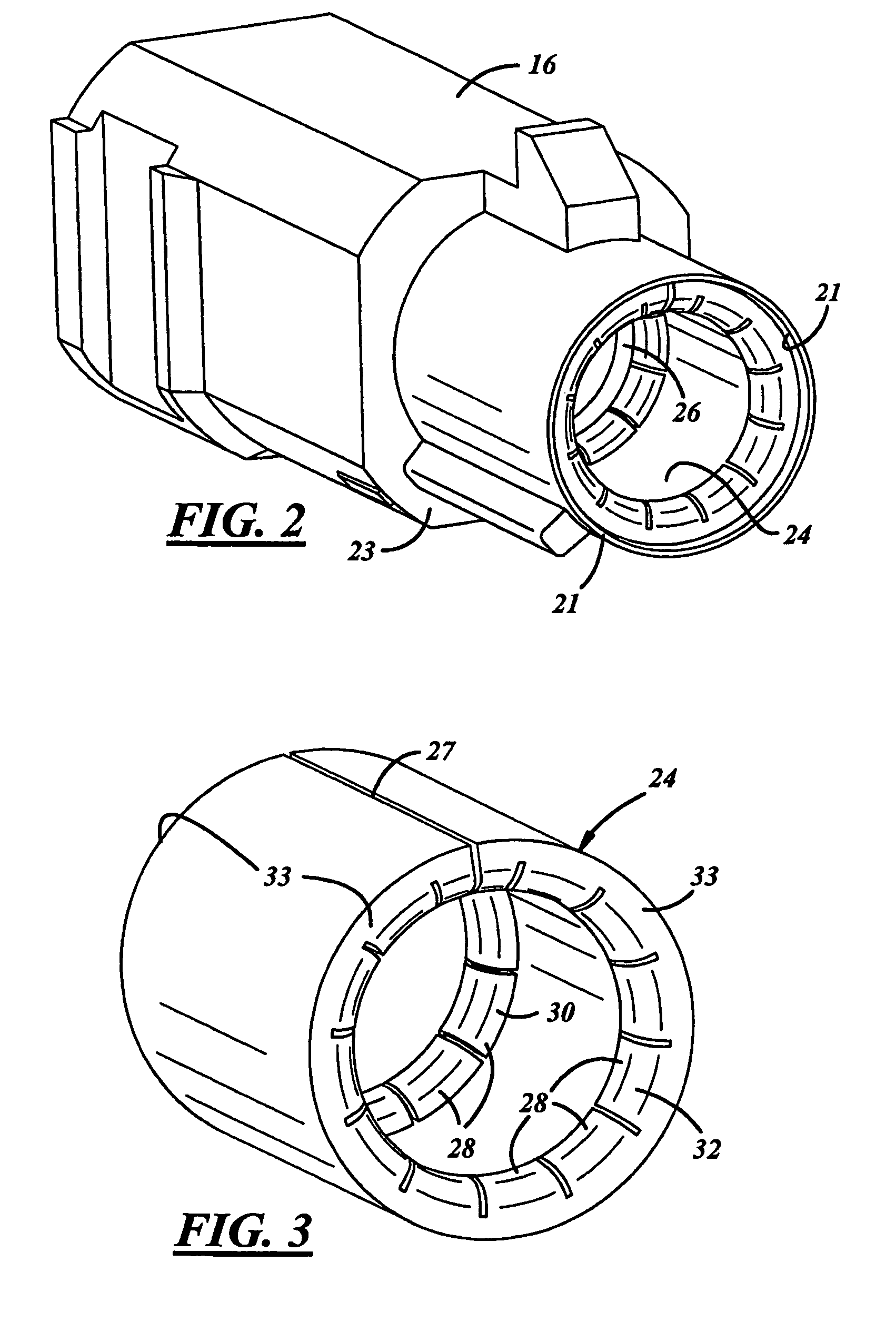
[0018]As more clearly shown in FIG. 2, the male plastic housing 14 has a tubular shield member 24 installed at its second end 21. The second end has a round cylindrical cavity 26 which snugly receives the tubular shield 24 by a press fit. Furthermore, the end 21 of cavity 26 may be necked down and the shield 24 may be radially compress to fit through the necked down end 21 and resiliently flex back to a larger diameter abutting against the cavity 26 after it clears the necked down end 21.

[0019]As more cl...


PUM


Abstract

An RF connector assembly has a first connector housing with a first end constructed for connectably receiving a terminal end for a first coaxial cable and a second connector housing with a first end constructed for connectably receiving a complementary terminal end for a second coaxial cable. The terminal end and complementary terminal end are complementarily constructed for engagement to each other. The first and second connector housing are constructed at their respective second ends to connect to one another. The first connector housing receives a tubular shield mounted about and connected to the respective terminal end. The tubular shield has a set of resilient radially inwardly extending contact fingers for electrically connecting about the complementary terminal end when the second connector housing is connected to the first connector housing.

Description

TECHNICAL FIELD[0001]The field of this invention relates to RF connectors.BACKGROUND OF THE INVENTION[0002]Radio Frequency (RF) connectors most often referred to simply as RF connectors are often used to connect coaxial cable while providing a certain degree of shielding. In recent times, the use of these connectors and coaxial cable has greatly increased in automotive applications with the advent of FM / AM radio, satellite based communication systems, e.g. OnStar™, keyless vehicle entry systems, navigations systems for eg. Global positioning systems, collision avoidance systems and other communication devices.[0003]The use of connectors for automotive usage has become so common that standards have been devised such as Fakra, and Uscar-17 specification of −45 dB. Other specifications such as low contact resistance have also been created. Some present day terminal connectors that meet these specifications are combination of plastic outer housings that snap fit together that include hi...

Claims


Application Information

Patent Timeline
Patent Type & Authority Patents(United States)
IPC IPC(8): H01R9/05
CPCH01R13/187H01R24/542H01R13/6272H01R2103/00H01R13/658
Inventor PHILLIPS, JR., WILLIAM THOMAS
Owner APTIV TECH LTD
Why Eureka
Try Eureka