Dynamic tension control apparatus and method for aero-mechanical conveyor

a technology of aeromechanical conveyor and control apparatus, which is applied in the direction of conveyors, conveyor parts, transportation and packaging, etc., can solve the problems of difficult access to the tube-joining clamp, insufficient mechanism, and inability of conventional tensioning devices to exert adequate tension on the rope, etc., and achieve the effect of quick response to changes

Active Publication Date: 2010-09-21
SPIROFLOW SYST
View PDF11 Cites 16 Cited by
  • Summary
  • Abstract
  • Description
  • Claims
  • Application Information

AI Technical Summary

Benefits of technology

[0005]The invention of the present application provides a dynamic tensioning apparatus. The present invention also provides tensioning apparatus that can quickly respond to changes in load on an aero-mechanical conveyor that may be caused by foreign objects such as bolts. The present invention also provides a pneumatic tensioning apparatus that is directly incorporated into a sliding seal assembly.
[0006]Therefore, it is an object of the present invention to provide an aero-mechanical conveyor having components which facilitate easy handling and installation, and provide low maintenance operation.
[0008]It is another object of the present invention to provide an aero-mechanical conveyor having a simple device for applying a generally constant tension on the rope assembly.

Problems solved by technology

The rope assembly can stretch to the point that a conventional tensioning device cannot exert adequate tension on the rope.
While prior art manual tension adjusting mechanisms exist for moving the head and tail pulley assemblies relative to each other to maintain the correct amount of tension on the rope assembly, such mechanisms are often inadequate.
In addition, the discharge end of the equipment is frequently inaccessible, making access to the tube-joining clamps challenging, and according to each method, the clamps have to be slackened and re-tightened.
Furthermore, once the tension has been adjusted, there is no guarantee that the tubes and the connecting spigots leading to the housings will be properly aligned, which makes jamming a possible cause of failure.

Method used


Image

  • Dynamic tension control apparatus and method for aero-mechanical conveyor
  • Dynamic tension control apparatus and method for aero-mechanical conveyor
  • Dynamic tension control apparatus and method for aero-mechanical conveyor

Examples


Embodiment Construction

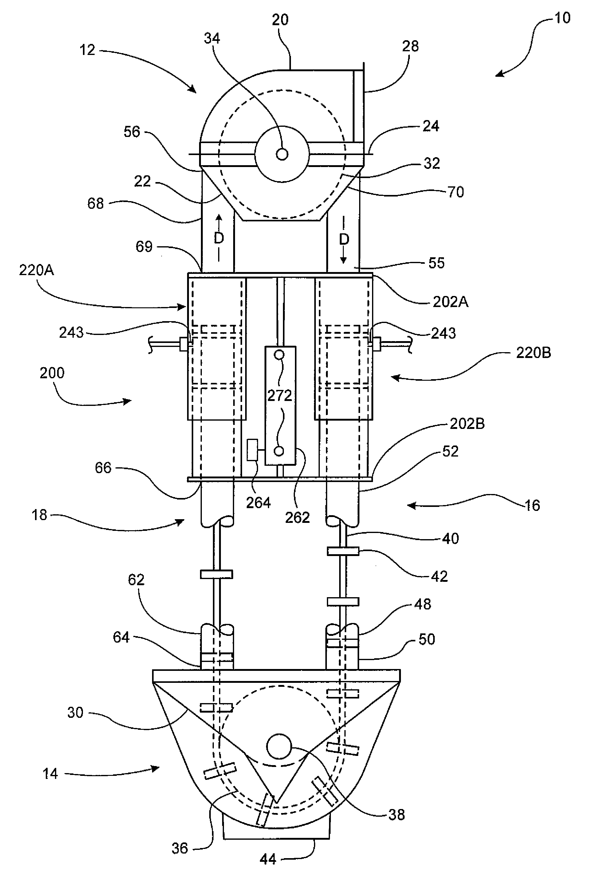
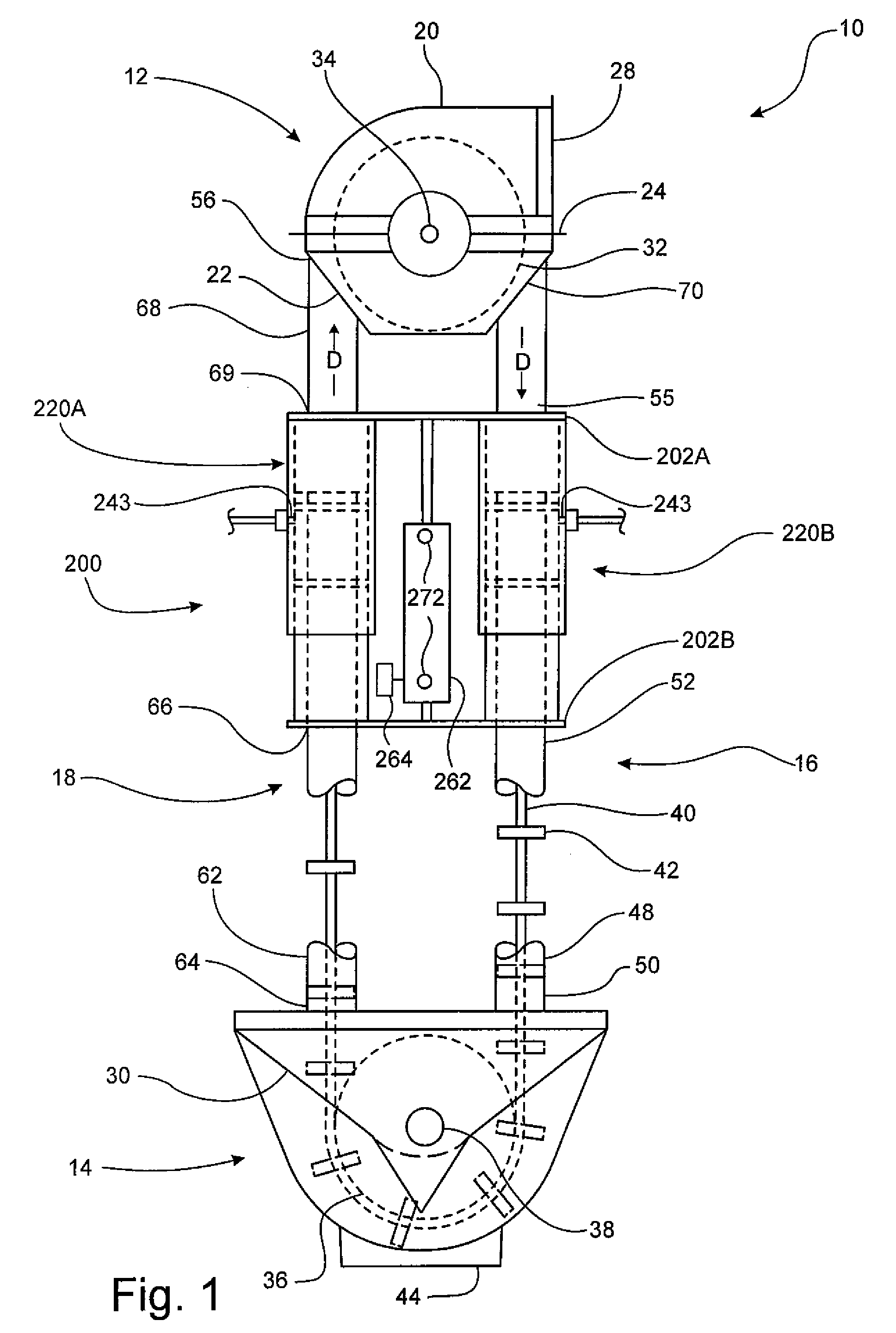
[0033]Referring now specifically to the drawings, an aero-mechanical conveyor according to the present invention is illustrated in FIG. 1 and shown generally at reference numeral 10. The conveyor 10 includes an upper housing 12 and an infeed housing 14 that are interconnected by inflow and outflow conveyor tubes 16 and 18. A head pulley assembly 32 that includes a sprocket is mounted on an upper shaft 34 that is positioned in the upper housing 12. Upper shaft 34 extends through one side of the upper housing 12 perpendicularly to the plane upon which rope assembly 40 travels. The upper shaft 34 is carried by and extends through bearing housings (not shown). The upper housing 12 includes a top portion 20 that is removably attached to a bottom portion 22 along first and second angle flanges 24. The top portion 20 is removable for permitting access to the interior of the upper housing 12 for inspection and maintenance, and defines an outlet opening 28 through which particulate matter ca...


PUM


Abstract

A tensioning assembly for use in an aero-mechanical conveyor for moving bulk materials. The conveyor includes upper and lower housings having head and tail pulley assemblies mounted therein. The tensioning assembly includes first and second extendable tubes that define sections of inflow and outflow conveyor tubes that interconnect the upper and lower housings. An endless rope assembly is disposed within the conveyor tubes and around the head and tail pulleys. An adjustable actuator is positioned in cooperative engagement with the first and second extendable tubes. When the actuator is in a first position, the extendable tubes have a first length and when the actuator is in a second position, the extendable tubes have a second length. The actuator is configured to move between the first position and the second position in response to changes in tension within the endless rope assembly as indicated by a signal from a tension measuring device.

Description

CROSS REFERENCE TO RELATED APPLICATIONS[0001]This application claims the benefit of Provisional Application No. 60 / 866,980, filed on Nov. 22, 2006.TECHNICAL FIELD AND BACKGROUND OF THE INVENTION[0002]This invention relates to a dynamic tension control apparatus and tensioning method for an aero-mechanical conveyor. Aero-mechanical conveyors are often used to convey powders and other particulate matter by entraining the particulate matter in a moving airstream. Such conveyors typically include an endless wire rope assembly upon which dividers are fastened and used for carrying the particulate matter. The rope assembly is typically carried on drive and driven pulleys enclosed within infeed, corner, and discharge housings in various configurations. The housings are interconnected by two tubes through which the rope assembly travels as it moves around the drive and driven pulleys. As the conveyor operates, forces are exerted on the rope assembly that can cause the rope assembly to stret...

Claims


Application Information

Patent Timeline
Patent Type & Authority Patents(United States)
IPC IPC(8): B65G23/44
CPCB65G23/44
Inventor HESKETH, DAVID FRANCIS
Owner SPIROFLOW SYST
Why Eureka
Try Eureka