
Ink jet printing apparatus and method for recovering the same

a printing apparatus and ink jet technology, applied in printing, other printing apparatus, etc., can solve the problems of inability to stably eject the ink, improper ejection, improper printing, etc., and achieve the effect of suppressing the increase in ink consumption

Inactive Publication Date: 2010-09-21
CANON KK
View PDF5 Cites 5 Cited by
  • Summary
  • Abstract
  • Description
  • Claims
  • Application Information

AI Technical Summary

Benefits of technology

This approach effectively manages ink accumulation in the ink receiving portion, reducing running costs and maintaining print head performance without the need for intricate mechanisms, allowing for a more efficient and cost-effective ink jet printing process.

Problems solved by technology

In this case, ink cannot be stably ejected by normal ink ejection energy, resulting in improper ejection.
In this case, an ink supply from an ink tank is hindered by the expanded bubbles, resulting in improper printing.
Moreover, ink scattering during preliminary ejection may result in, for example, contamination of the cap and its surroundings.
However, recent printers, the sizes of which tend to be reduced, may limit the space in which the ink receiving portion is installed.
Accordingly, the need to avoid the interference between these mechanisms and the ink receiving portion makes it difficult to design the channel through which ink is guided from the ink receiving portion to the waste ink absorbing portion as well as the shape of the ink receiving portion.
For example, the ink receiving portion may have to be partly constricted; the ideal design may be impossible.
As a result, the deposit may block the channel.
In this case, the deposit may disadvantageously overflow or contact the ejection opening formed surface.
However, the technique disclosed in Japanese Patent Laid-Open No. 7-323574 disadvantageously increases the width of the printing apparatus and the number of components to complicate the mechanism and control.
This disadvantageously increases ink consumption and thus running costs.
However, this technique does not remove the deposit itself.
Therefore, if preliminary ejection is frequently carried out or viscous ink is used, the amount of ink deposit itself apparently increases.

Method used


Image

  • Ink jet printing apparatus and method for recovering the same
  • Ink jet printing apparatus and method for recovering the same
  • Ink jet printing apparatus and method for recovering the same

Examples


first embodiment

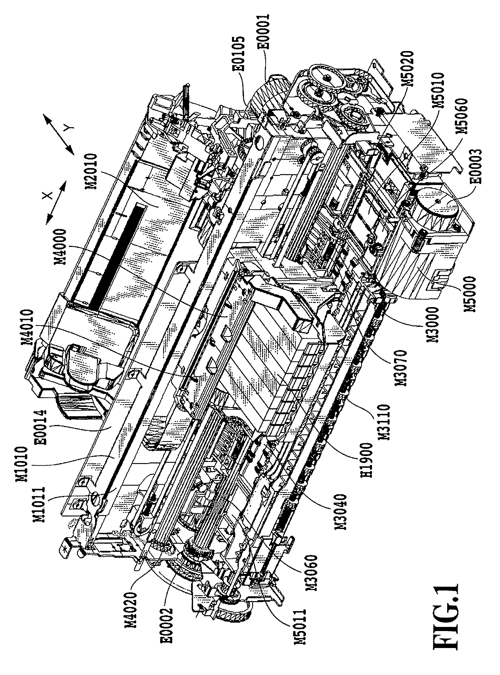
[0036]FIG. 1 is a perspective view showing an ink jet printing apparatus to which the present invention is applied according to a first embodiment and from which an outer covering portion has been removed to expose an internal mechanism. The printing apparatus main body according to the present embodiment has a sheet feeding portion, a sheet conveying portion, a sheet discharging portion, a carriage portion, a cleaning portion, and the outer covering portion. The arrangement and operation of each of these portions will be described below.

Cleaning Section

[0037]The cleaning portion cleans a print head (described below). The cleaning portion comprises a suction recovery portion including a pump M5000 and a cap M5010 that prevents the print head from being dried. The cleaning portion further comprises a wiping portion including a blade M5020 that cleans an ejection surface of the print head, and a cleaning motor E0003 that generates a driving force required to drive the wiping portion.

[...

second embodiment

[0083]Now, a second embodiment of the present invention will be described.

[0084]FIGS. 8A to 8E schematically show a preliminary ejecting operation sequence on the ink receiving portion M5010 according to the second embodiment of the present invention. The preliminary ejection operation sequence in FIGS. 8A to 8E is based on the basic preliminary ejection operation sequence in FIGS. 6A to 6E.

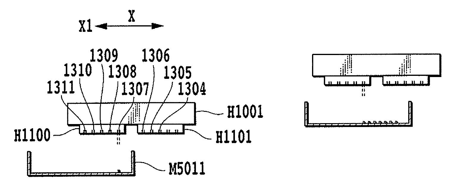
[0085]The present embodiment also counts ejections from each nozzle in the ejecting portion1311 of the print head H1001 during a preliminary ejecting operation on the ink receiving portion M5011. The special color ink 2, corresponding to the ejecting portion 1311 (see FIG. 4) of the print head H1001, contains a less soluble color material than the seven other color inks. The special color ink 2 is thus difficult to re-disperse even when mixed with any of the seven other color inks and accumulates very easily.

[0086]The carriage M4000 scans toward the ink receiving portion M5011 (in an X1 direction...


PUM


Abstract

An amount of deposit in an ink receiving portion can be controlled using an inexpensive configuration which does not require any complicated mechanisms or control and which avoids increasing ink consumption. An ejection control section controls ejecting of ink from a printing section into an ink receiving portion. The printing section has a first ink ejecting portion that ejects ink that accumulates easily in the ink receiving portion and a second ink ejecting portion that ejects ink that is hard to accumulate in the ink receiving portion. The ejection control section changes the landing position, in the ink receiving portion, of the ink ejected from the ink ejecting portions depending on the status of accumulation of the ink in the ink receiving portion.

Description

BACKGROUND OF THE INVENTION[0001]1. Field of the Invention[0002]The present invention relates to a serial scanning ink jet printing apparatus that performs a printing operation by scanning a print head in a direction crossing a direction in which print media are conveyed. In particular, the present invention relates to an ink jet printing apparatus in which in order to maintain the proper ejecting performance of a print head, ink is ejected into an ink receiving portion provided at a position opposite a scan area for the print head, to recover the performance of the print head. The present invention also provides a method for recovering the ink jet printing apparatus.[0003]2. Description of the Related Art[0004]An ink jet printing apparatus outputs an image by ejecting a liquid such as ink from an ink jet print head (hereinafter simply referred to as a print head) onto a print medium in accordance with input image data. Thus, a maintenance technique for maintaining the proper ink ej...

Claims


Application Information

Patent Timeline
Patent Type & Authority Patents(United States)
IPC IPC(8): B41J2/165
CPCB41J2/1752B41J29/38B41J29/393
Inventor YOSHIKAWA, HIROKAZUMIZOGUCHI, YOSHITOIDE, DAISAKU
Owner CANON KK
Learn More