Vehicular turning control apparatus and method

a technology of turning control and control apparatus, which is applied in the direction of electric control, process and machine control, instruments, etc., can solve the problems of developing energy loss in vehicular driving and braking forces, automatic deceleration through brake control and engine control, and unpleasant feeling for the vehicle driver, so as to suppress unpleasant feeling and suppress energy loss of braking and driving forces

Active Publication Date: 2010-09-28
NISSAN MOTOR CO LTD
View PDF22 Cites 8 Cited by
  • Summary
  • Abstract
  • Description
  • Claims
  • Application Information

AI Technical Summary

Benefits of technology

[0004]It is, therefore, an object of the present invention to provide vehicular turning control apparatus and method which can suppress the unpleasant feeling given to the vehicle driver and can suppress the energy loss of the braking and driving forces.

Problems solved by technology

However, specific techniques of the automatic deceleration through the brake control and the engine control are not disclosed.
For example, in a case where the brake control causes an abrupt automatic braking force to be developed in a state where an accelerator pedal is depressed by a vehicle driver, an unpleasant feeling is given to the vehicle driver.
An energy loss in vehicular driving and braking forces is developed by an interference of the driving force and the braking force.

Method used


Image

  • Vehicular turning control apparatus and method
  • Vehicular turning control apparatus and method
  • Vehicular turning control apparatus and method

Examples


first embodiment

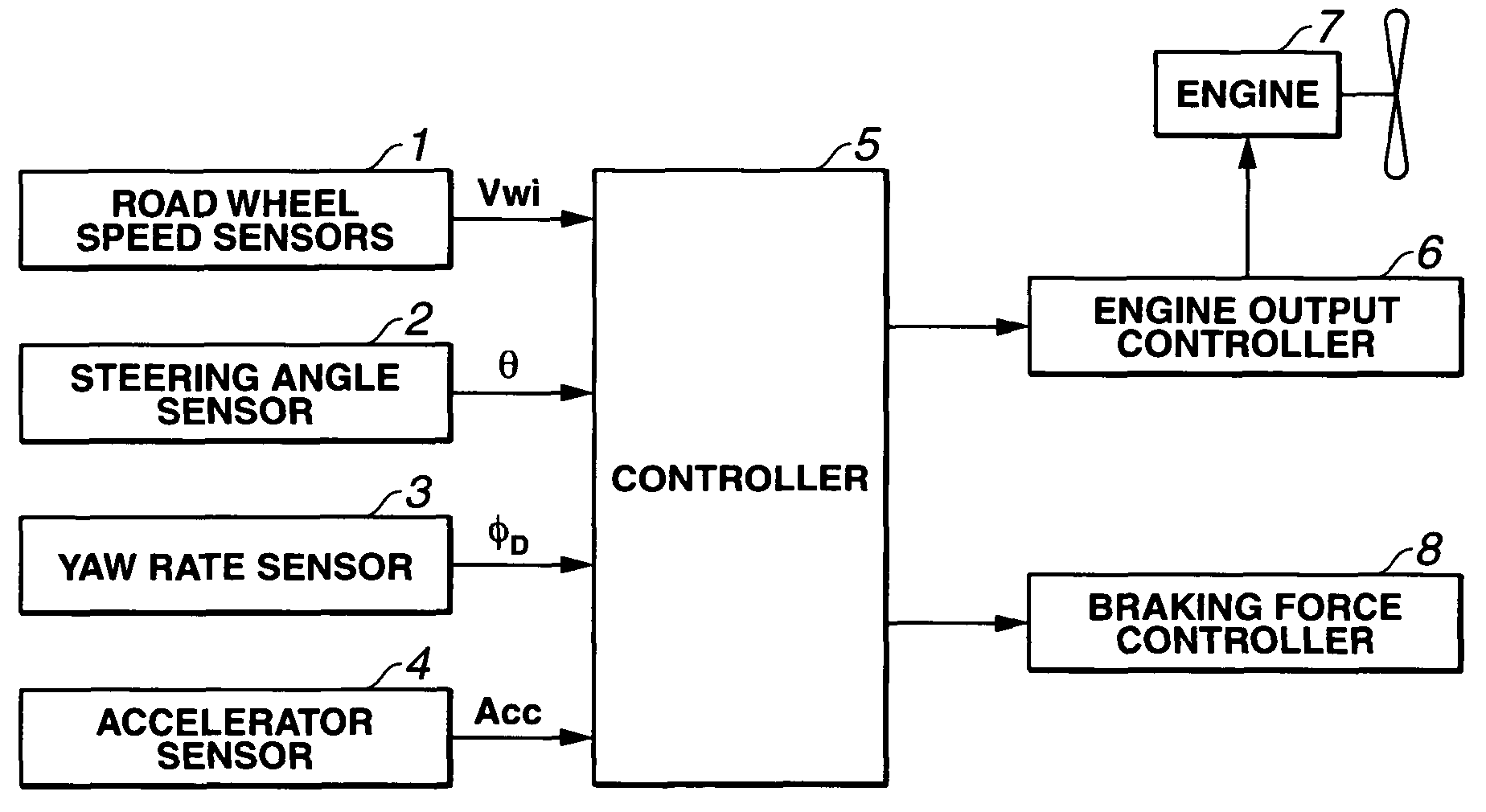
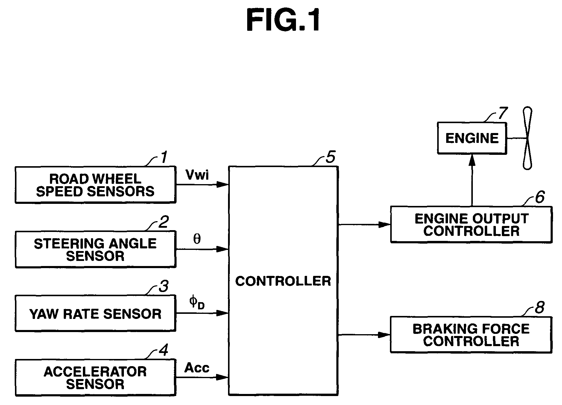
[0035]At the subsequent step S2, controller 5 calculates turning velocity V on the basis of each road wheel velocity Vwi. It is noted that, in the first embodiment, turning velocity V is calculated on the basis of each road wheel velocity Vwi. The present invention is not limited to this. A forward-and-backward acceleration (longitudinal acceleration) of a vehicle body may be detected by means of an acceleration sensor and may calculate turning velocity V with the longitudinal acceleration in mind. At the subsequent step S3, controller 5 calculates a vehicular body yaw rate φ in accordance with a block diagram shown in FIG. 4.

[0036]First, referring to a control map as shown in FIG. 5, controller 5 calculates a yaw rate estimated value φE in accordance with steering wheel steering angle θ and turning velocity V. It is noted that the control map used for the calculation of yaw rate estimated value φE is set in such a manner that, with a lateral axis as steering wheel steering angle θ ...

third embodiment

[0060]In the third embodiment, the suppression quantity of the engine output is varied continuously unlimitedly in accordance with accelerator opening angle Acc. However, the present invention is not limited to this. The engine output suppression quantity may be varied in a stepwise manner in accordance with accelerator opening angle Acc or may be varied at one step. Furthermore, the suppression quantity of the engine output may be varied in a curved manner in accordance with accelerator opening angle. However, the present invention is not limited to this. The suppression quantity of the engine output may be varied linearly in accordance with the magnitude of accelerator opening angle Acc.

[0061]In the third embodiment, whenever the turning control procedure is executed, the suppression quantity of the engine output is calculated and the engine output is suppressed in accordance with the suppression quantity. However, the present invention is not limited to this. For example, with th...


PUM


Abstract

In turning control apparatus and method for an automotive vehicle, the vehicle through at least one of a deceleration action section and a brake mechanism is decelerated when a turning state of the vehicle satisfies a predetermined condition, an accelerator manipulated variable by a vehicle driver is detected, and the deceleration through the brake mechanism is limited and the deceleration through the deceleration action section is carried out, when the detected accelerator manipulated variable exceeds a predetermined value (α).

Description

BACKGROUND OF THE INVENTION[0001]The present invention relates to vehicular turning control apparatus and method which achieve a stable turning of the vehicle.[0002]A Japanese Patent No. 2600876 issued on Jan. 27, 1997 exemplifies a previously proposed turning control apparatus for an automotive vehicle. In the previously proposed vehicular turning control apparatus, an automatic deceleration of the vehicle is carried out in such a manner that a turning velocity and a radius of turn do not exceed respective limits on a turning performance of the vehicle so as to achieve a stable turning.SUMMARY OF THE INVENTION[0003]In the previously proposed vehicular turning control apparatus disclosed in the Japanese Patent, an automatic deceleration is carried out through a brake control and an engine control. However, specific techniques of the automatic deceleration through the brake control and the engine control are not disclosed. For example, in a case where the brake control causes an abru...

Claims


Application Information

Patent Timeline
Patent Type & Authority Patents(United States)
IPC IPC(8): B60T8/24B60T8/1755B60W10/04B60W10/06B60W10/18B60W10/188B60W10/192B60W30/00F02D29/02F02D45/00
CPCB60T8/1755B60T8/246B60W10/06B60W10/184B60W30/02B60W30/045B60W40/064B60W40/11B60W40/112B60W40/114B60T2201/16B60W2520/10B60W2540/10B60W2540/106B60W2710/06B60W2710/18
Inventor ISHIMOTO, TAKESHI
Owner NISSAN MOTOR CO LTD
Why Eureka
Try Eureka