Reversible door with integral pivot pin

a technology of pivot pin and hinge, which is applied in the field of doors, can solve the problems of unfulfilled problems, hindered smooth hinge operation, and unwanted noise, and achieve the effect of convenient and convenient manual operation

Active Publication Date: 2010-10-05
MIDMARK
View PDF59 Cites 10 Cited by
  • Summary
  • Abstract
  • Description
  • Claims
  • Application Information

AI Technical Summary

Benefits of technology

[0010]The present invention is directed to a door assembly for use on an animal cage or other enclosure comprising at least one pivot pin assembly integrally formed with the door and a cooperating hinge secured to the enclosure. The pivot pin assembly includes a vertically oriented pivot pin integrally formed with at least one horizontal support member extending from the pivot pin across a portion of the door. A hinge barrel formed within the hinge is configured to receive the pivot pin such that the pivot pin may rotate within the barrel, thereby moving the door from an open to a closed position. Given that the pivot pin is integrally formed with the door in a vertically aligned position relative to the door, the load is more evenly distributed throughout the door and hinge than with conventional systems utilizing a separate hinge pin. Furthermore, door removal and reattachment can be easily and conveniently accomplished manually without the need for additional tools.
[0011]In a preferred embodiment, the door includes at least two pivot pin assemblies and each pivot pin assembly comprises horizontal support members extending from the upper and lower ends of the pivot pin at about a 90-degree angle from the pivot pin. The pivot pins are aligned along one side of the door and the horizontal support members extend from the pivot pins horizontally across a majority of the door toward the opposite side of the door. The use of upper and lower horizontal support members further enhances correct alignment of the door so as to minimize, if not fully eliminate, the potential for sagging or twisting over time. In this preferred embodiment, a two-piece bushing is fitted around the pivot pin and then secured within the hinge barrel. The bushing is preferably formed of a low friction material and is preferably self-lubricating, so as to enable the pivot pin to freely rotate within the bushing in a smooth and quiet manner. The bushing may include a key or other device for locking the bushing in the hinge barrel so as to prevent movement of the bushing as the pivot pin rotates. Support shoulders may be provided along the outer upper edge of the hinge barrel to present horizontal surfaces on which the upper horizontal support member may rest. A reinforcing member may also be embedded within the hinge to strengthen the hinge and ensure more equal distribution of the load.

Problems solved by technology

Thus, smooth operation of the hinge is hindered by the fact that the edges of the barrel segments of the door leaf engage the edges of the barrel segments of the interlocked frame hinge.
This contact between the door leaf and frame leaf may interfere with operation of the hinge and can result in unwanted noise.
Furthermore, in such a configuration, the weight of the door on the barrel segments translates to a twisting moment on the barrel segments of the leaves.
While this sagging can be somewhat alleviated by providing larger hinges with more barrel segments, or more commonly, by using several hinges on a single door to distribute the weight of the door between the hinges, the problem is not fully eliminated.
Over time and continued use, the hinge connection weakens and the door begins to sag and become more difficult to close.
Removal and reattachment of traditionally hinged doors can be difficult.
This can be especially difficult as the hinge pin is often stuck within the barrel segments of the hinge leaf.
Reattaching the door can also be challenging because the individual barrel segments on each hinge leaf must be perfectly aligned for receipt of the hinge pin.
Even when new, this can be a tricky process due to a door's size, shape and weight.
In addition, when doors, frames, or hinge leafs are warped, damaged or out of square, reattachment can be nearly impossible.

Method used


Image

  • Reversible door with integral pivot pin
  • Reversible door with integral pivot pin
  • Reversible door with integral pivot pin

Examples


Embodiment Construction

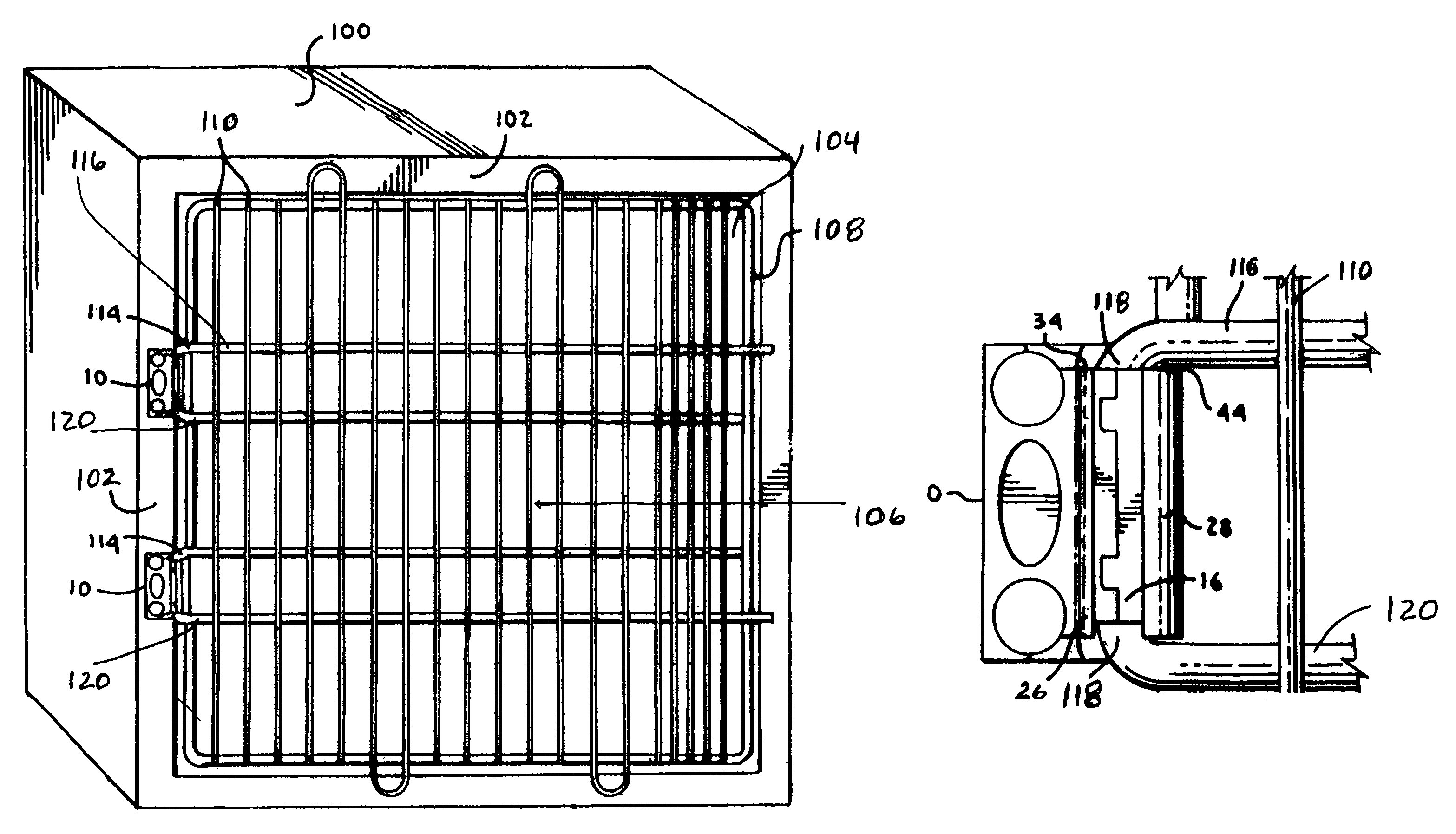
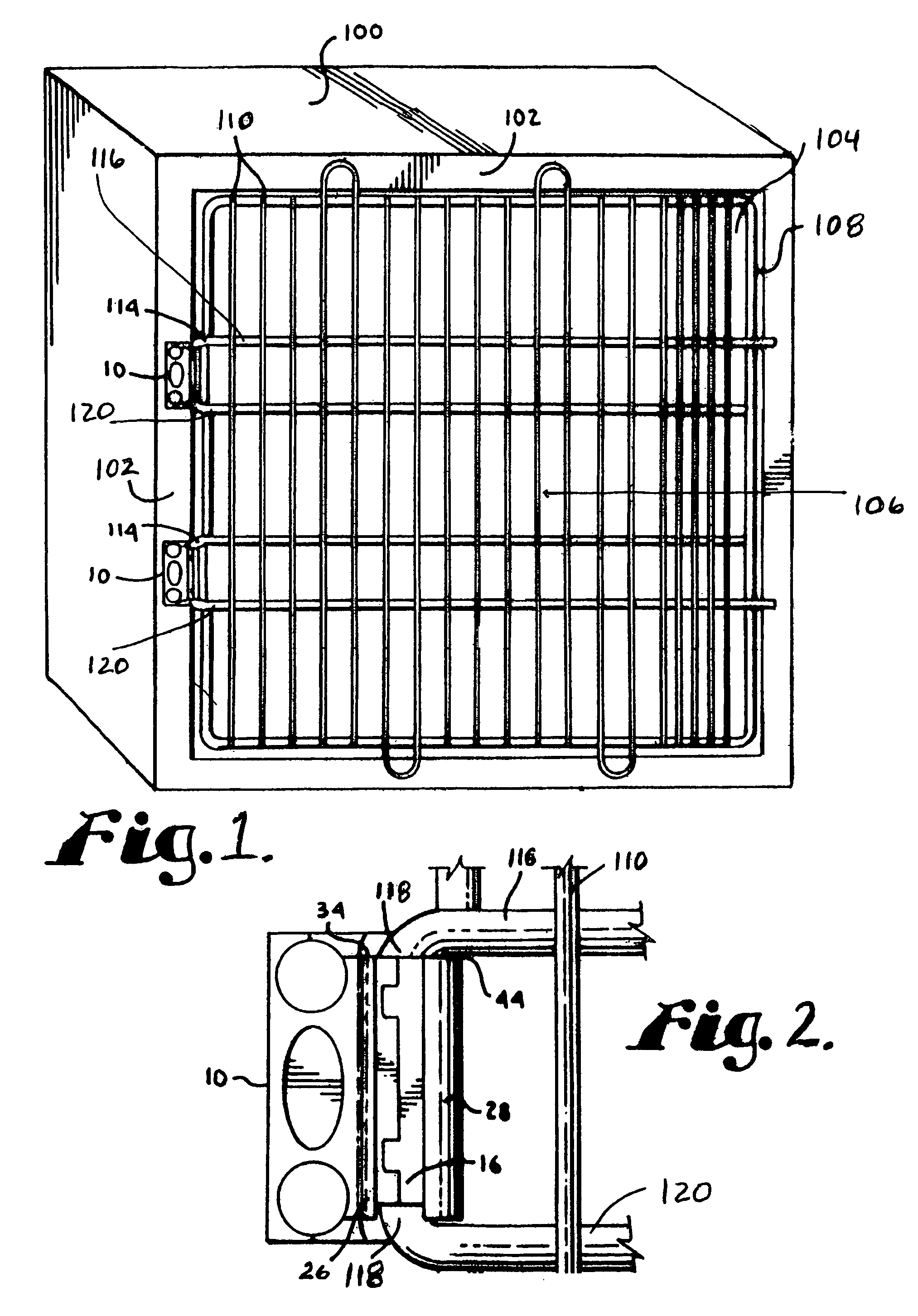
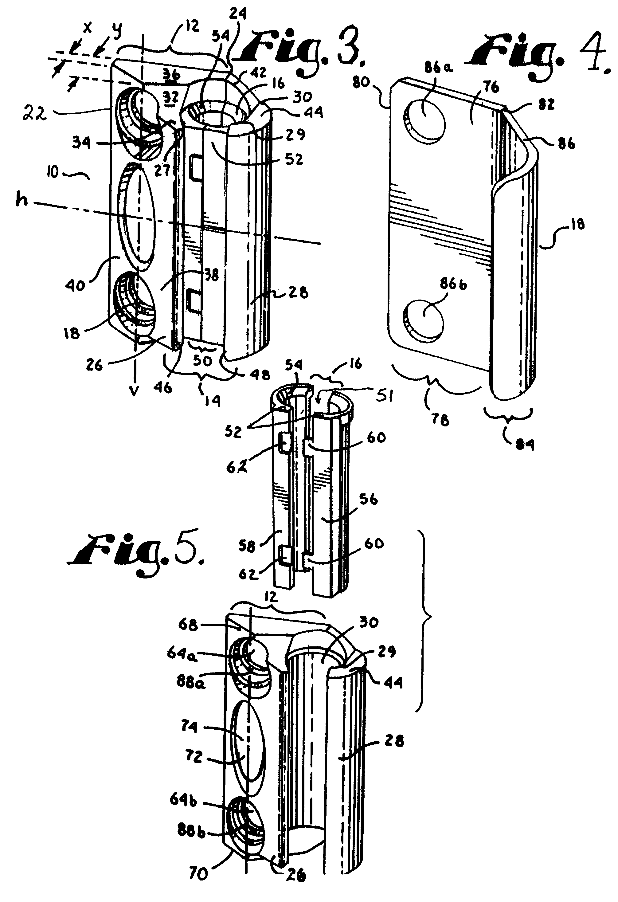
[0022]A door assembly in accordance with an exemplary embodiment of the present invention is depicted in FIGS. 1 through 7. While the invention will be described in detail hereinbelow with reference to this exemplary embodiment, it should be understood that the invention is not limited to the specific configuration shown in this embodiment. Rather, one skilled in the art will appreciate that a variety of configurations may be implemented in accordance with the present invention.

[0023]Looking to FIGS. 1 and 2, an animal cage 100 includes a front wall 102 having an opening 104 over which door 106 is pivotally mounted such that door 106 may be pivoted from a closed position (as shown) to an open position (not shown) to enable access to the interior of the cage. Door 106 is connected to the cage by two hinges 10 secured on the left side of the cage adjacent the opening. Door 106 is comprised of an outer frame 108 formed of metal rod sized and configured to correspond and fit within the ...


PUM


Abstract

A door assembly for pivotally securing a door to an animal enclosure or other enclosure. The door assembly comprises a pivot pin assembly integrally formed with the door and a hinge secured to the enclosure adjacent the opening. The pivot pin assembly preferably comprises a vertically oriented pivot pin integrally formed with upper and lower horizontal support members extending from upper and lower ends of the pivot pin across a portion of the door. The pivot pin is fitted within a hinge barrel formed within the hinge in a manner to permit the pivot pin to rotate within the barrel such that the door may be pivoted from an open to a closed position.

Description

CROSS-REFERENCE TO RELATED APPLICATIONS[0001]None.STATEMENT REGARDING FEDERALLY SPONSORED RESEARCH OR DEVELOPMENT[0002]Not applicable.BACKGROUND OF THE INVENTION[0003]1. Field of the Invention[0004]The present invention relates to doors for animal enclosures and other enclosures and is more specifically directed to an improved door assembly for pivotally connecting a door to an enclosure in a manner that more evenly distributes the load of the door, reduces the potential for sagging and allows for removal and reattachment of the door with greater ease.[0005]2. Description of Related Art[0006]Animal cages, pens, kennels, runs, and other types of enclosures are generally accessed and closed by pivoting doors secured to the side of the opening in the enclosure via hinges that allow the door to be moved between open and closed positions. Various configurations of hinges are known, with the most common type being an interlocking leaf type comprising two separate leaf pieces attached with...

Claims


Application Information

Patent Timeline
Patent Type & Authority Patents(United States)
IPC IPC(8): E05D7/10
CPCA01K1/03A01K31/02E05D7/1066E05Y2900/40E06B11/04Y10T16/53996Y10T16/53613Y10T16/5393Y10T16/54028Y10T16/53987Y10T16/53615Y10T16/540256Y10T16/5363
Inventor MATTESON, MICHAEL L.
Owner MIDMARK
Why Eureka
Try Eureka