
Passive type RFID semiconductor device, IC tag, and control method

a technology of rfid semiconductor and ic tag, which is applied in the direction of burglar alarm mechanical actuation, burglar alarm by hand-portable article removal, instruments, etc., can solve the problems of reading/writing errors the wrong data for correct data, and reducing the reliability of read data. , to achieve the effect of improving the reliability of read data

Active Publication Date: 2010-10-05
RENESAS ELECTRONICS CORP
View PDF46 Cites 6 Cited by
  • Summary
  • Abstract
  • Description
  • Claims
  • Application Information

AI Technical Summary

Benefits of technology

The invention provides a semiconductor device, an IC tag, and a control method for executing a secure data reading operation with improved reliability. The device generates a power supply voltage based on a received radio signal, detects the voltage, and uses different operation voltages for reading and writing data. The control unit executes the data reading operation based on the power supply voltage, ensuring reliable performance of the reading operation. This invention improves the reliability of read data and enhances the efficiency of RFID technology.

Problems solved by technology

That is, the control circuit for controlling the reading operation cannot operate in response to a read command from the reader / writer, so the IC tag cannot respond to the command from the reader / writer.
That is, the IC tag can operate in accordance with the read command from the reader / writer, but data is not normally read from the nonvolatile memory, with the result that wrong data is read and the read data is sent to the reader / writer.
Thus, the reader / writer mistakes the wrong data for correct data.
Hence, there is a possibility that the data read from the IC tag is wrong, which reduces a reliability of the read data.
If the data read from the IC tag is wrong, an erroneous operation is executed.

Method used


Image

  • Passive type RFID semiconductor device, IC tag, and control method
  • Passive type RFID semiconductor device, IC tag, and control method
  • Passive type RFID semiconductor device, IC tag, and control method

Examples


first embodiment

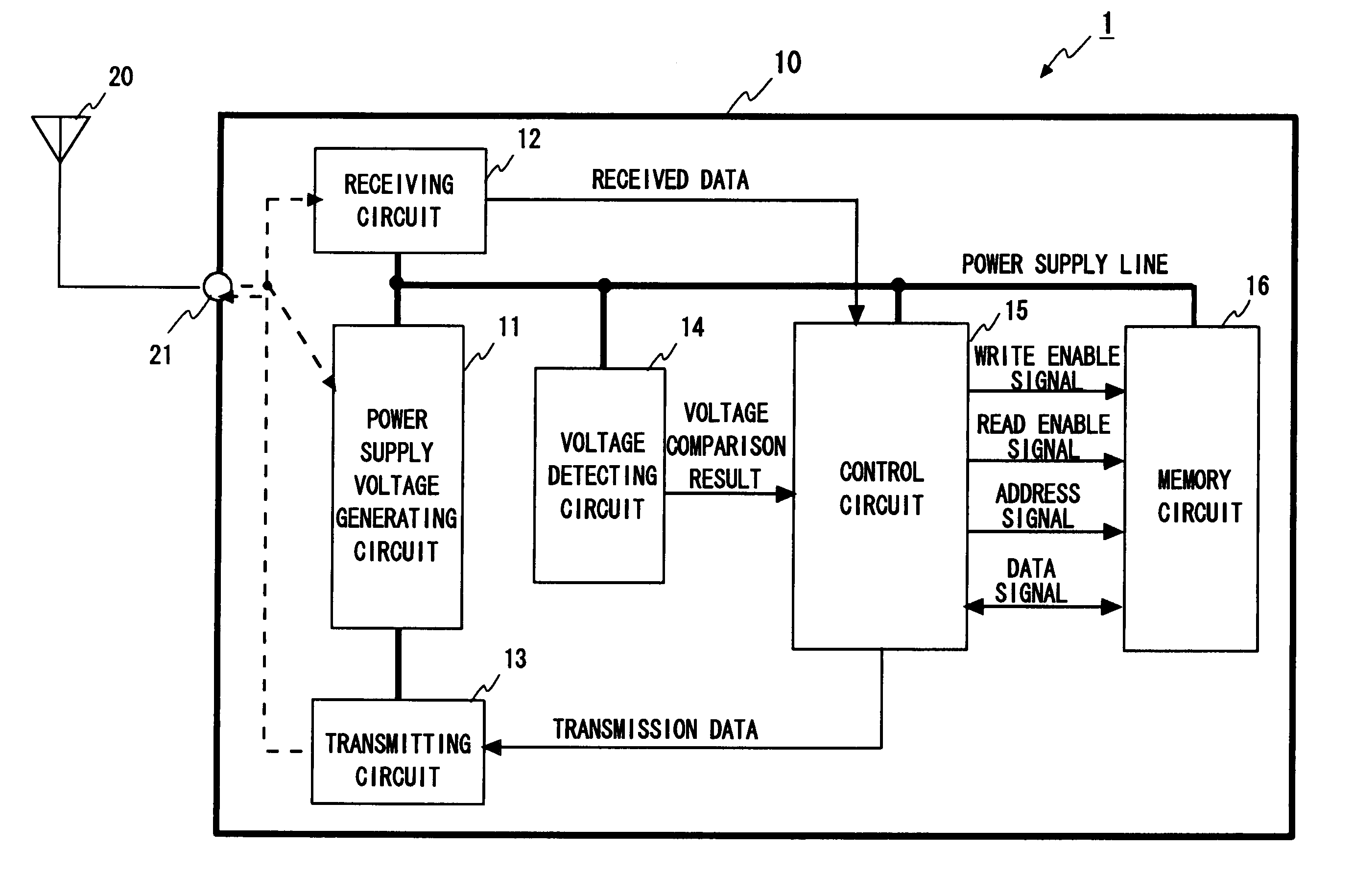
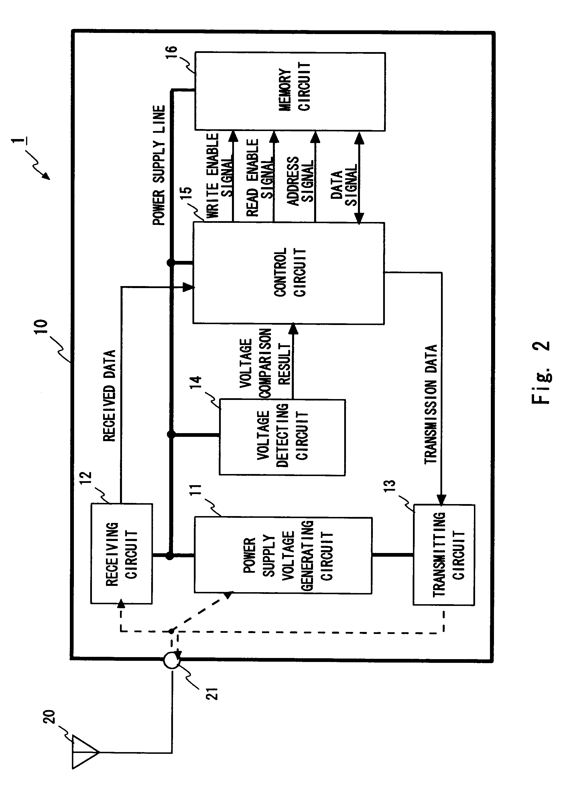
[0047]To begin with, a communication system using an IC tag according to a first embodiment of the present invention is described. The IC tag and communication system according to this embodiment have a feature that a reading operation is executed if a power supply voltage generated by the IC tag is higher than a memory read circuit operation marginal voltage value.

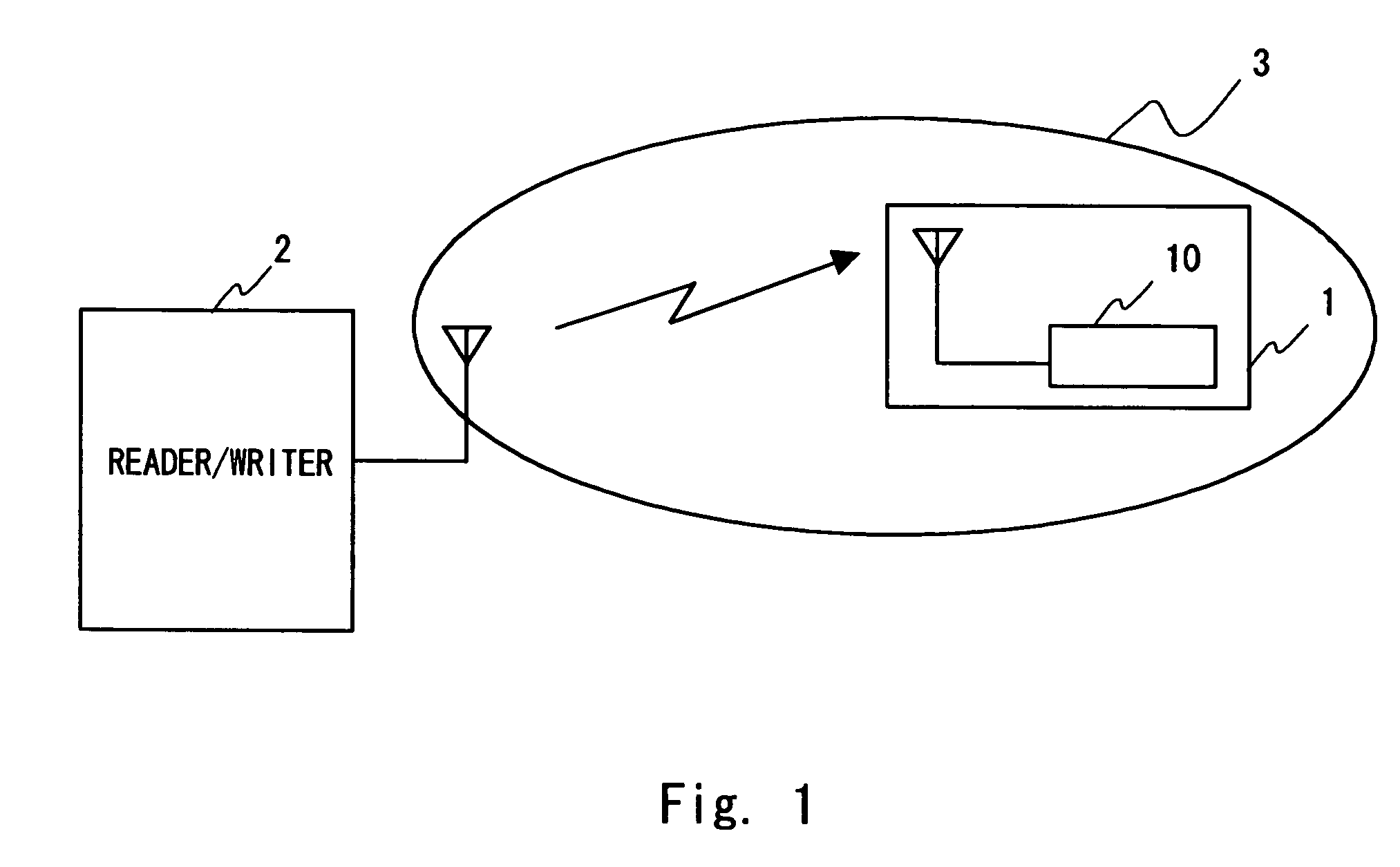
[0048]Referring to FIG. 1, the configuration of the communication system using the IC tag of this embodiment is described. This communication system includes, as shown in FIG. 1, an IC tag 1 and a reader / writer 2. In the communication system, the IC tag 1 communicates with the reader / writer 2 by radio.

[0049]The reader / writer 2 is connected with a computer (not shown) in a communicable form, and functions to write desired data to a memory circuit in the IC tag 1 or read written data or a tag ID as an identifier of the IC tag 1 from the IC tag 1 in accordance with an instruction of the computer.

[0050]In the case of writing / ...

second embodiment

[0085]Next, a communication system using an IC tag according to a second embodiment is described. The IC tag and the communication system of this embodiment have a feature that a temporary storage circuit other than the memory circuit is provided to the IC tag. Incidentally, the communication system of this embodiment has the same configuration as that of FIG. 1, so its description is omitted. Then, the configuration of the IC tag is described.

[0086]FIG. 7 is a block diagram showing the configuration of the IC tag according to this embodiment. In FIG. 7, the same components as those of FIG. 2 are denoted by like reference numerals, and their description is omitted. The IC tag 1 has a register 17 in the control circuit 15 in addition to the components of FIG. 2. Other components of the control circuit 15 are the same as those of FIG. 4, and the configuration of the memory circuit 16 is the same as that of FIG. 5.

[0087]The register 17 is an example of a temporary storage circuit. For ...

third embodiment

[0093]Next, a communication system using an IC tag according to a third embodiment of the present invention is described. The IC tag and the communication system of this embodiment have a feature that a reader / writer obtains voltage comparison results as results of evaluating the power supply voltage in the IC tag. Incidentally, the communication system of this embodiment has the same configuration as that of FIG. 1, and the IC tag has the same configuration as that of FIG. 7, so their description is omitted, and the following description is focused on an operation of the communication system.

[0094]FIG. 9 is a flowchart of a data reading operation in the communication system of this embodiment. In FIG. 9, the same steps as those of FIGS. 6 and 8 are denoted by like reference symbols, and their description is omitted.

[0095]FIG. 9 shows an example where data is read based on a voltage comparison result sent to the reader / writer 2 from the IC tag 1. As shown in FIG. 9, first, radio wav...


PUM


Abstract

To provide a semiconductor device capable of securely executing a reading operation to improve a reliability of read data, an IC tag including the semiconductor device, and a control method for the IC tag. A semiconductor device according to an embodiment of the present invention includes: a power supply voltage generating circuit for generating a power supply voltage based on a received radio signal; a power supply voltage generating circuit for detecting the power supply voltage; a memory area for storing predetermined data; a reading / writing circuit using different operation voltages for reading data from the memory area and writing data to the memory area; and a control circuit for executing a data reading operation for the memory area based on a detected power supply voltage.

Description

BACKGROUND OF THE INVENTION[0001]1. Field of the Invention[0002]The present invention relates to a passive type RFID semiconductor device, an IC tag, and a control method. In particular, the present invention relates to a semiconductor device for generating a power supply voltage based on a received radio signal, an IC tag including the semiconductor device, and a control method for the IC tag.[0003]2. Description of Related Art[0004]In recent years, attentions have been paid to a technique regarding RFID (Radio Frequency IDentification) as a product automatic identifying technique for affixing an IC tag having product specific information written thereto, and scanning this information using a radio antenna to manage a product in real time, in merchandise logistics management at the factory and article management at a retail shop.[0005]The above RFID IC tag (hereinafter simply referred to as “IC tag”) does not incorporate a battery since a power supply voltage is generated based on ...

Claims


Application Information

Patent Timeline
Patent Type & Authority Patents(United States)
IPC IPC(8): H04Q5/22G08B13/14G06K7/00G06K19/00H04B5/48
CPCG06K19/0701G06K19/0723
Inventor SATOU, KOUTAROU
Owner RENESAS ELECTRONICS CORP
Learn More