Handheld water misting fan with improved air flow

a technology of improved air flow and water misting fan, which is applied in the direction of ventilation system, heating type, separation process, etc., can solve the problems of increased humidity, decreased comfort, and aesthetics of water misting fan, and achieves improved aesthetics and durability

Active Publication Date: 2010-10-05
O2COOL
View PDF8 Cites 111 Cited by
  • Summary
  • Abstract
  • Description
  • Claims
  • Application Information

AI Technical Summary

Problems solved by technology

For the benefit of the cooling, the cost is increased humidity, which can decrease comfort.
In the case of designs such as Steiner '495, the water misting fan exhibits a problem with aesthetics and durability.
The durability problem comes from the interface between the reservoir, sprayer and the fan enclosure.
Further, conventional water misting fans have vulnerable triggers and attachment collars where the sprayer mates with the top of the bottle.
The aesthetic problem comes from the compromises of the separable component design.
In the instance of portable bottle type misting fan designs, there is an unsightly, cheap-looking screw collar that detracts from the smooth lines of the fan head.
Similarly, the use of the standard sprayer requires the use of the blocky nozzle and cheap-looking trigger that detract from the overall design.
The design does not allow us to hide the chunky-looking sprayer and nozzle within the enclosure because of size and functional reasons.
The grip is often uncomfortable because it is too large around for smaller hands or the weight is not well balanced.
What is lacking in the prior art is a water misting fan that can withstand the rigors of outdoor use while still looking sleek and stylish.

Method used


Image

  • Handheld water misting fan with improved air flow
  • Handheld water misting fan with improved air flow
  • Handheld water misting fan with improved air flow

Examples


Embodiment Construction

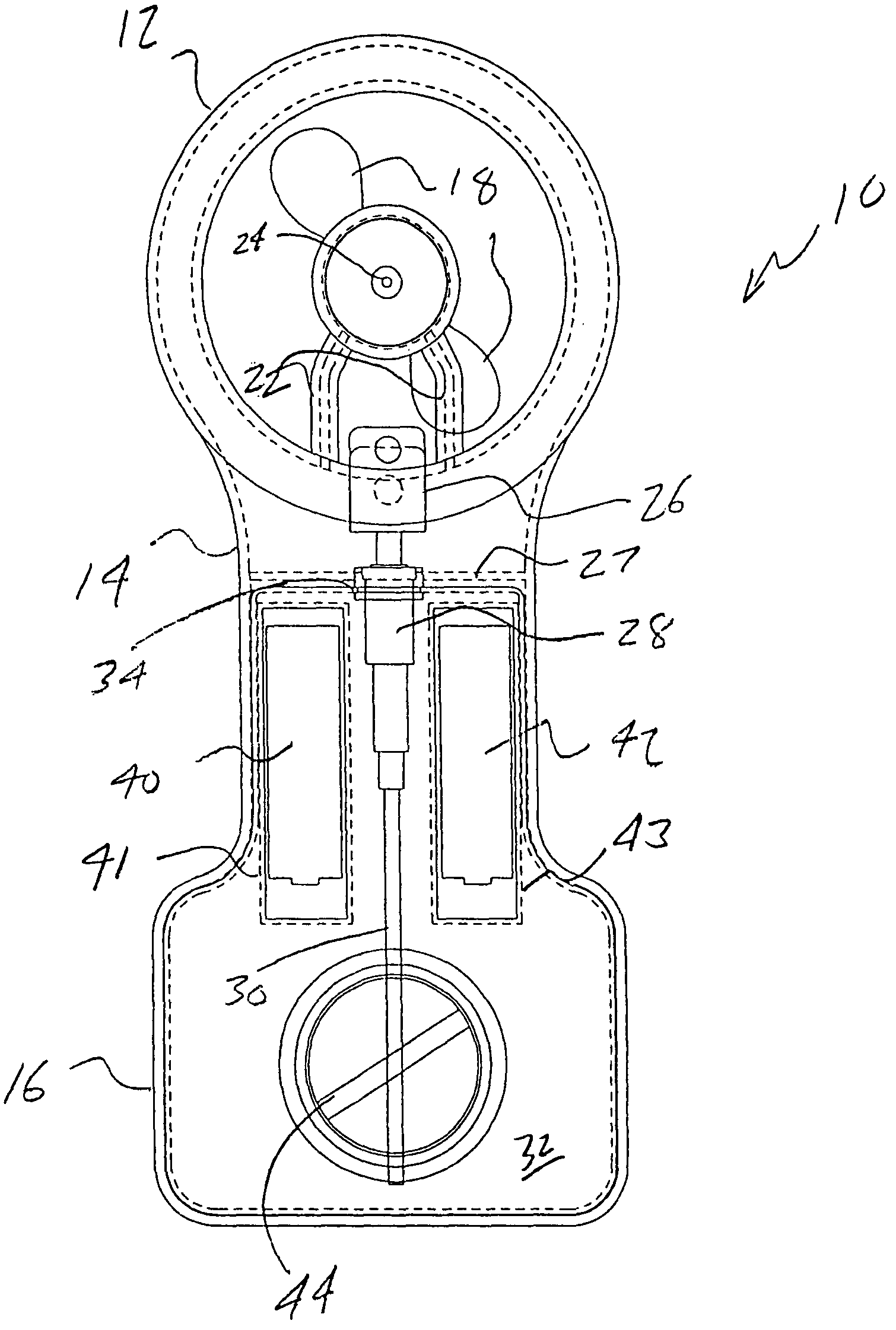
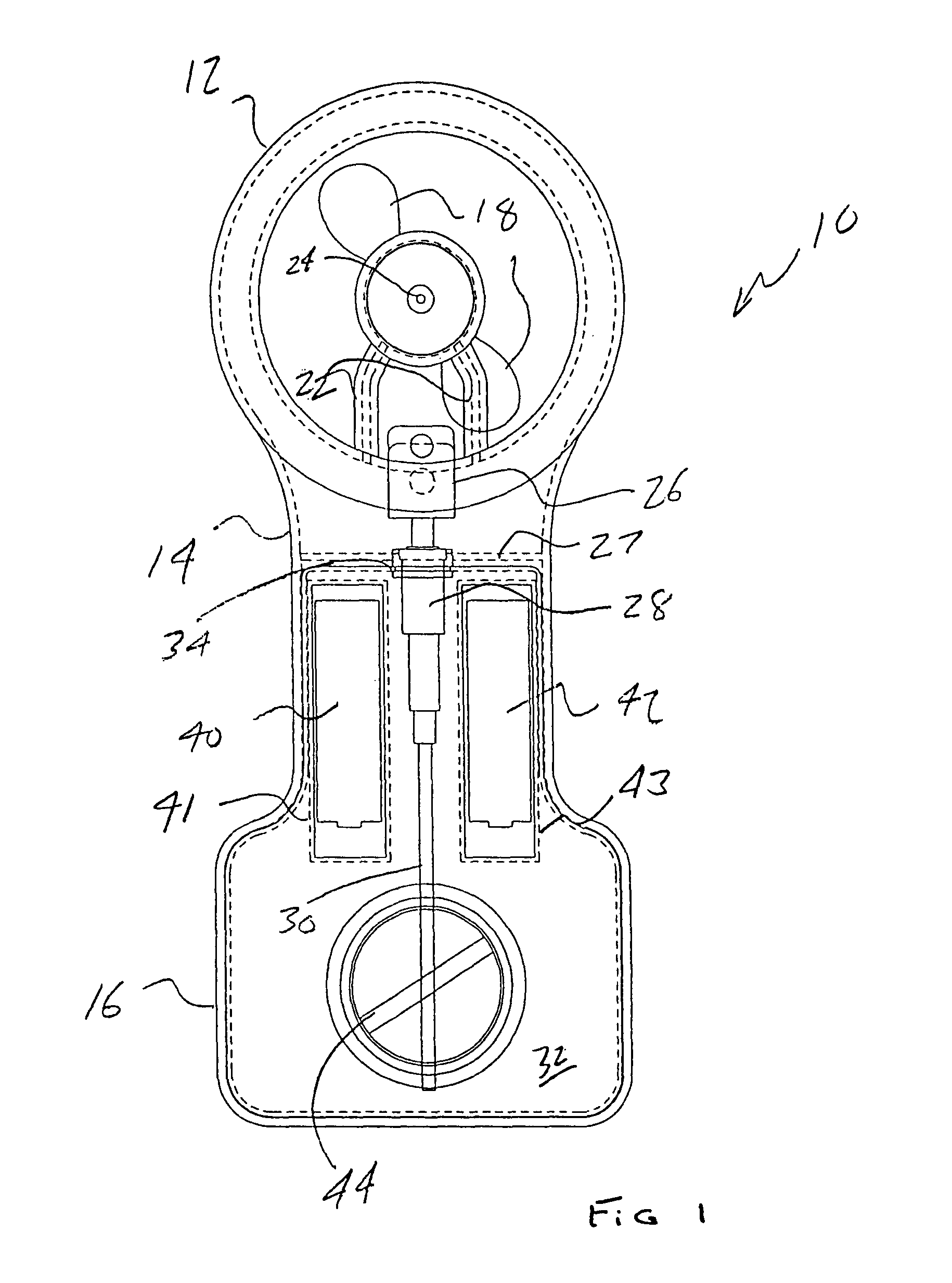
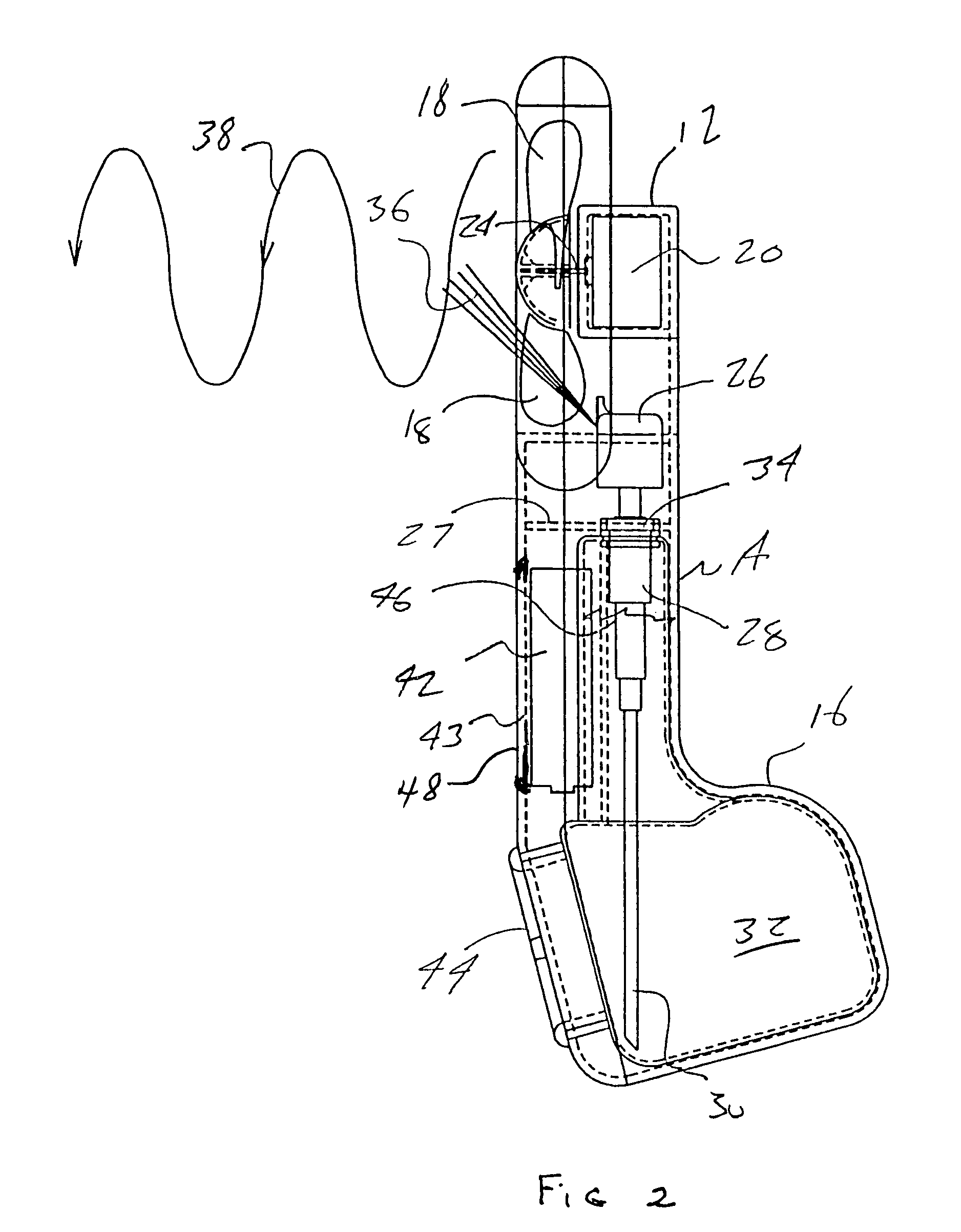
[0025]Referring now to FIG. 1, a front view is shown at 10 of an improved water misting fan according to a first preferred embodiment of the present invention. As will be subsequently described, the illustrations provided herein consist of front and side views in two-dimension, and which show various internal components in phantom.

[0026]Referring again to FIG. 1, as well as to the side view of FIG. 2, a main body of the misting fan 10 is typically constructed of a one-piece and integral body and includes an upper shroud portion 12, an intermediate neck portion 14 and a lower fluid reservoir holding portion 16. Encased within the shroud is a rotating impeller (see pair of blades 18) driven by a rearwardly mounted motor 20. A pair of motor supports (or struts) 22, see FIG. 1, support the motor 20. A pair of motor supports (or struts) 22, see FIG. 1, support the motor 20 and associated impeller, see further motor drive shaft 24 (FIG. 2), and are configured to exhibit a minimal cross se...


PUM

PropertyMeasurementUnit
areaaaaaaaaaaa
poweraaaaaaaaaa
volumeaaaaaaaaaa

Abstract

The present invention is directed to an improved handheld water misting fan device wherein the power source compartment is positioned within the device at a location remote from the fan motor thereby to remove any structure from the area bounded by the fan shroud. The relocation of the power source compartment leaves the area bounded by the shroud substantially unobstructed thereby to improve air flow. The device is formed in a dog bone shaped configuration to provide a narrow handle section for improved grippability, and an enlarged fluid reservoir at the lower end thereof for greater reservoir capacity.

Description

I. FIELD OF THE INVENTION[0001]The present invention discloses an improved handheld water misting fan. More specifically, the present invention discloses a handheld version misting fan both rugged in construction and more stylish than conventional handheld water misting fan. The present invention improves upon one or more of the features which include air flow, fluid volume of the reservoir and grippability.II. BACKGROUND OF THE RELEVANT ART[0002]The water misting fan is a device for providing personal and environmental cooling by spraying atomized water droplets into an air stream. The droplets evaporate thereby drawing heat out of the surrounding air. Non-evaporated droplets impinge on the user and further evaporation draws heat out of clothing and skin of the user or surrounding surfaces. These are sometimes called “swamp coolers”. For the benefit of the cooling, the cost is increased humidity, which can decrease comfort. Swamp coolers work poorly in confined or very humid enviro...

Claims


Application Information

Patent Timeline
Patent Type & Authority Patents(United States)
IPC IPC(8): B01F3/04
CPCF24F5/0035F24F6/14F24F7/007Y02B30/545Y02B30/54
Inventor JUNKEL, ERICCHEN, YUNG
Owner O2COOL
Why Eureka
Try Eureka