Magnetic light assembly associated method

a technology of magnetic light and associated methods, which is applied in the direction of fixed installation, lighting and heating apparatus, and support devices for lighting, etc., can solve the problems of not including magnets, not providing a mechanism for supporting a device other than manually, and example not providing hooks as an alternate stability mechanism

Inactive Publication Date: 2010-10-05
AYALA SERGIO
View PDF5 Cites 3 Cited by
  • Summary
  • Abstract
  • Description
  • Claims
  • Application Information

AI Technical Summary

Benefits of technology

[0018]The assembly further includes a hook shaped fastener directly and rotatably engaged with a top edge of the light-emitting source for effectively allowing the magnetic light assembly to be suspended above a ground level.
[0022]The method further includes the step of: removably attaching a protective mesh screen to an anterior face of the top housing and thereby shielding the light source from undesirable foreign debris.

Problems solved by technology

Although utility lights are very useful devices, a frequently encountered problem is finding a place to hook the light onto that provides adequate light to illuminate the work area.
Unfortunately, this prior art example does not include a magnet as an alternative stabling mechanism.
Unfortunately, this prior art example does not provide a mechanism for supporting a device other than manually.
Unfortunately, this prior art example does not provide hooks as an alternate stability mechanism.

Method used


Image

  • Magnetic light assembly associated method
  • Magnetic light assembly associated method
  • Magnetic light assembly associated method

Examples


Embodiment Construction

[0029]The present invention will now be described more fully hereinafter with reference to the accompanying drawings, in which a preferred embodiment of the invention is shown. This invention may, however, be embodied in many different forms and should not be construed as limited to the embodiment set forth herein. Rather, this embodiment is provided so that this application will be thorough and complete, and will fully convey the true scope of the invention to those skilled in the art. Like numbers refer to like elements throughout the figures.

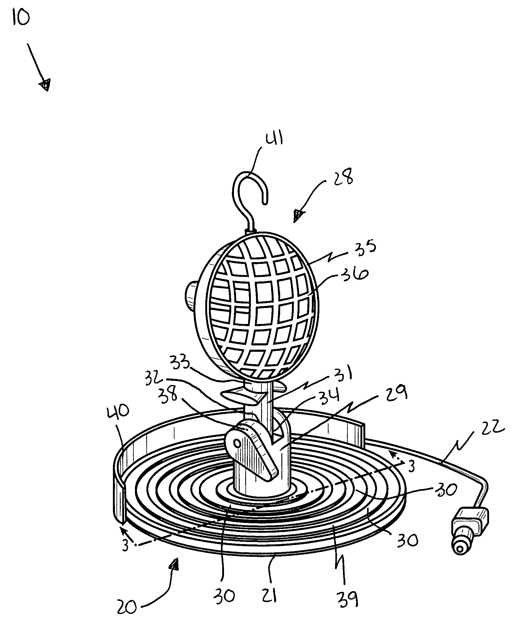
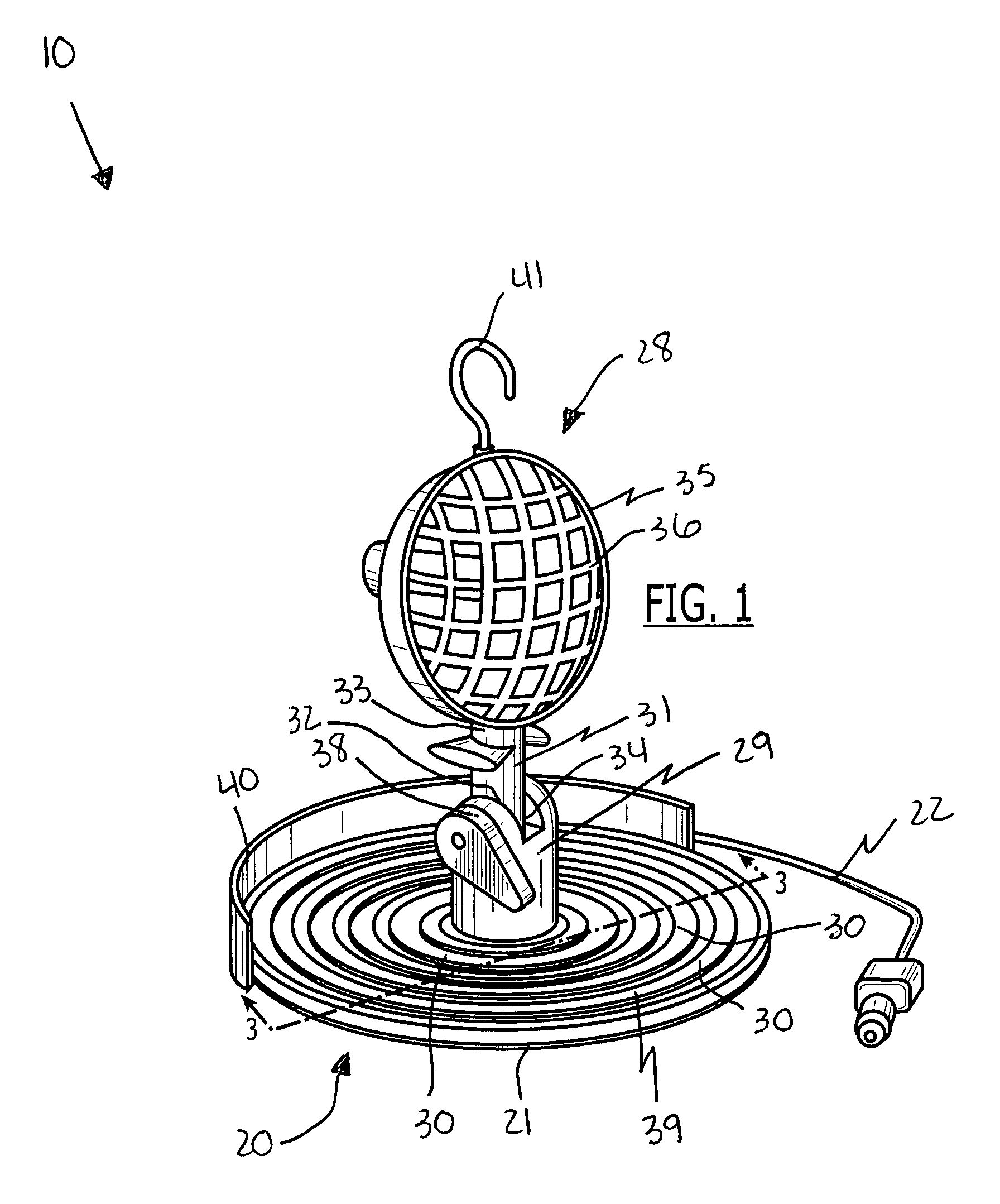
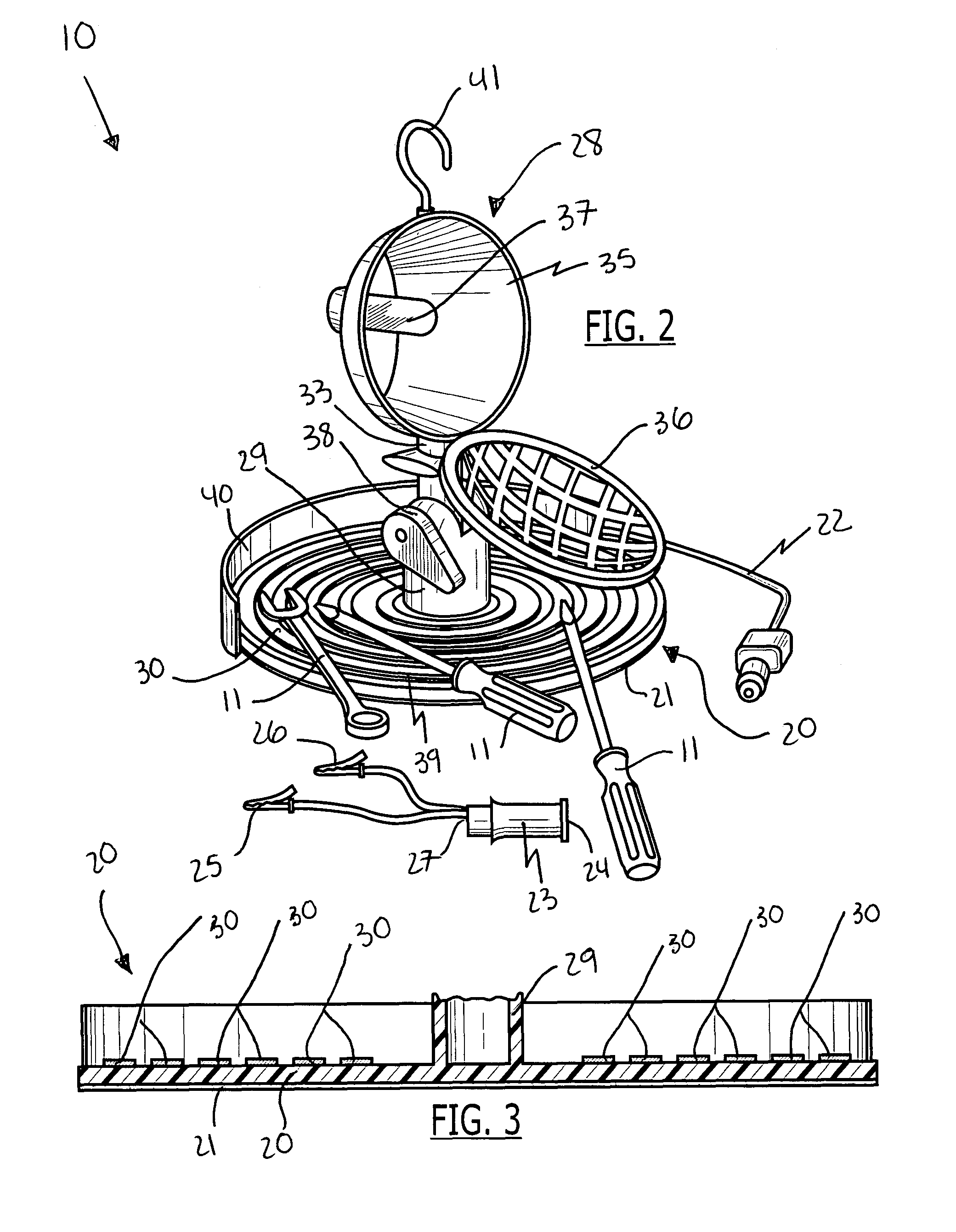
[0030]The assembly of this invention is referred to generally in FIGS. 1-3 by the reference numeral 10 and is intended to protect a multifunctional and portable magnetic light assembly. It should be understood that the assembly 10 may be used to provide light in many different setting and should not be limited to providing light in only those settings mentioned herein.

[0031]Referring initially to FIGS. 1, 2 and 3, a multifunctional and portab...


PUM


Abstract

A multifunctional and portable magnetic light assembly includes a magnetic base section with a unitary and single body provided with a planar bottom surface and a power cable provided with an adaptor removably mated directly thereto. The assembly further includes a power-operated light-emitting source electrically mated to the power cable and directly coupled to the base section in such a manner that the light-emitting source is selectively adjustable along an arcuate path oriented above the base section. The light emitting source further includes an anchor shaft and an illuminable light source. The assembly further includes a mechanism for removably securing a plurality of existing hand tools to the base section.

Description

CROSS REFERENCE TO RELATED APPLICATIONS[0001]This application claims the benefit of U.S. Provisional Application No. 60 / 849,187, filed Oct. 4, 2006, the entire disclosures of which are incorporated herein by reference.STATEMENT REGARDING FEDERALLY SPONSORED RESEARCH OR DEVELOPMENT[0002]Not Applicable.REFERENCE TO A MICROFICHE APPENDIX[0003]Not Applicable.BACKGROUND OF THE INVENTION TECHNICAL FIELD[0004]This invention relates to light assemblies and, more particularly, to a magnetic light assembly for providing portable light while keeping hand tools engaged with the light assembly.PRIOR ART[0005]Over the years, many different types of tools have been developed and, nowadays, a tool exists for virtually every possible need. With the advent of power tools, accomplishing many tasks has became much easier and less time consuming. Most power tools (other than battery operated tools) are equipped with a fairly short power cable and extension cords are commonly used to provide extra length...

Claims


Application Information

Patent Timeline
Patent Type & Authority Patents(United States)
IPC IPC(8): B25B23/18
CPCB25B11/002B25H3/06F21L14/02F21V21/0965F21V33/0084F21V21/30F21V27/005
Inventor AYALA, SERGIO
Owner AYALA SERGIO
Why Eureka
Try Eureka