Transverse rod connector

a connector and transverse rod technology, applied in the field of surgery, can solve the problems of not providing flexibility in adjusting the devices, not allowing a surgeon to connect multiple rods, and unable to adapt to the physiological characteristics of patients, so as to facilitate the actuation of the sphere

Inactive Publication Date: 2010-10-05
ALPHATEC SPINE INC
View PDF9 Cites 55 Cited by
  • Summary
  • Abstract
  • Description
  • Claims
  • Application Information

AI Technical Summary

Benefits of technology

[0015]The setscrew may have a conical surface (or other surface, e.g., spherical) on the interior portion to directly actuate the spheres against the rods. The setscrew may also indirectly actuate the spheres / circular members by using an insert with a relieved portion to accommodate the setscrew. The insert preferably includes an inclined surface at the sphere contact portion to facilitate actuation of the spheres. The forces that force a sphere outward may also tend to deform the insert against the setscrew. Thus, increased rotational force on the setscrew is transformed into a setscrew gripping action by the insert itself. This gripping action may prevent the setscrew from loosening during dynamic loading conditions (for example).
[0016]The rod slots may be oversized to accommodate the capturing of rods which are initially skewed. Accordingly, in one embodiment of the invention, the action of tightening the setscrew captures the rods and persuades the rods into a substantially parallel configuration (for example) —this is accomplished by forcing the rods against a lateral surface of the rod slot. The openings of the lateral slot at the bilateral rod slots may be smaller than the space in which the spheres translate in order to prevent expulsion of the spheres from the interior body.

Problems solved by technology

These devices do not provide flexibility when adjusting the devices either prior to, during, or after their placement into the patient.
Thus, these devices force a surgeon to utilize a specific configuration, leaving very little room for adjustment in accordance with patient's physiological characteristics and needs.
Further, these devices do not allow a surgeon to connect multiple rods by actuating a single setscrew mechanism.

Method used


Image

  • Transverse rod connector
  • Transverse rod connector
  • Transverse rod connector

Examples


Embodiment Construction

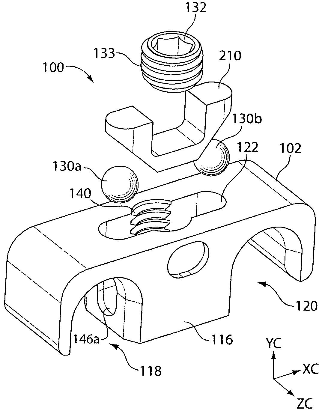
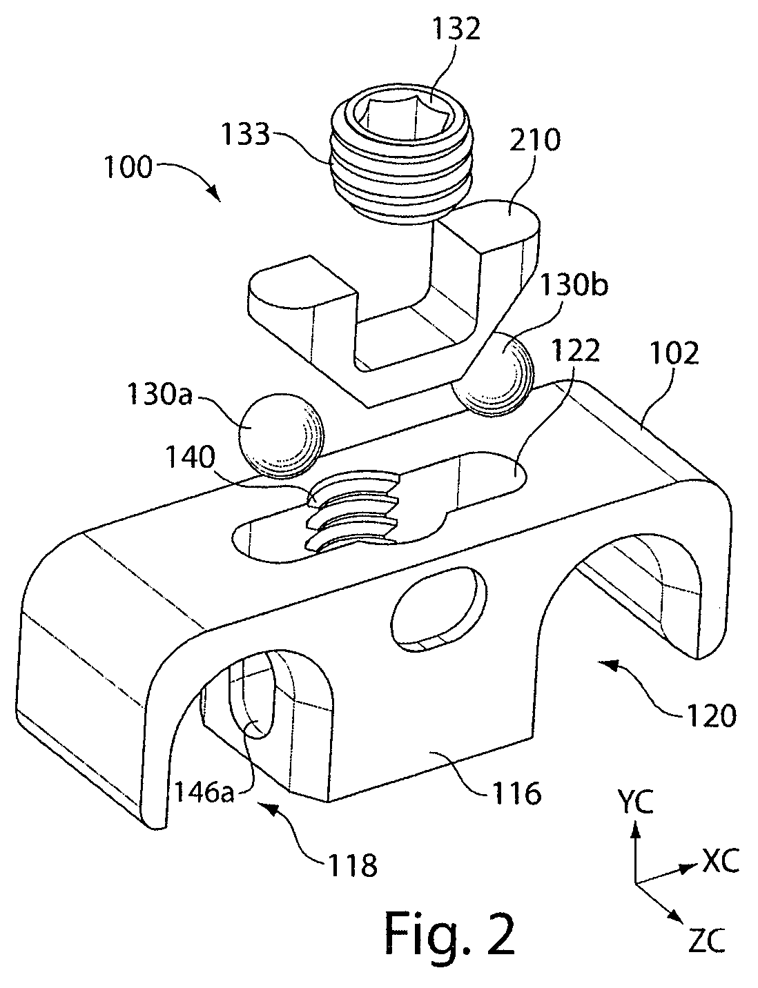
[0023]Some embodiments of the present invention relates to the field of surgery, and more specifically to a bone alignment rod (e.g. transverse rod) connector that may hold at least one and preferably two (or more) rods. The rod can be a cervical rod, a posterior rod, or any other rod used during medical applications.

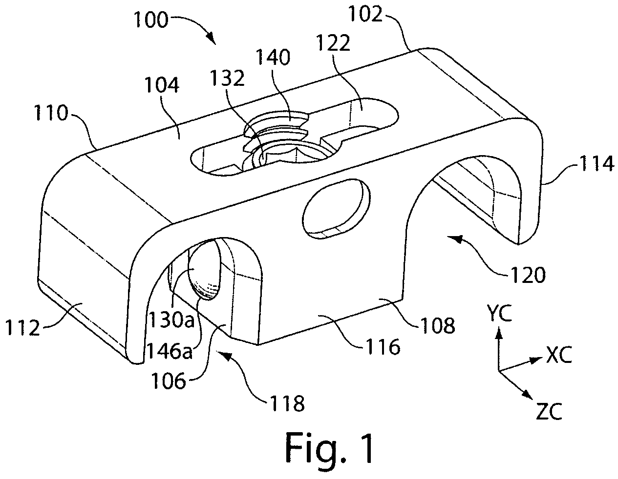
[0024]FIG. 1 illustrates a perspective view of the transverse rod connector 100, having a housing 102 which includes a top portion 104, a bottom portion 106, a front portion 108, a back portion 110, and side portions 112, 114. As illustrated, an x-y-z coordinate system can be used to better visualize the spatial orientation of elements in the housing 102. Accordingly, the top and bottom portions 104, 106 are disposed in an x-z coordinate field, the side portions 112, 114 are disposed in the y-z coordinate field, and the front and back portions 108, 110 are disposed in the x-y coordinate field.

[0025]The housing 102 further includes a central portion 116, which, in the pr...


PUM


Abstract

Embodiments of the present invention are directed to bone alignment rod connectors, and more particularly to traverse rod connectors. In one embodiment, the connector includes a housing having an opening configured to accommodate at least one rod, a setscrew assembly configured to secure the at least one rod when the at least one rod is placed in the opening. The setscrew assembly includes a setscrew and at least one circular / spherical object configured to interact with the setscrew when the setscrew is inserted in the housing. Upon insertion of the setscrew, the at least one spherical object is configured to laterally move towards the at least one rod to secure the at least one rod inside the housing.

Description

CROSS-REFERENCE TO RELATED APPLICATIONS[0001]The present application claims priority to U.S. Provisional Application No. 60 / 725,031, to Laurence et al., filed Oct. 7, 2005, and titled “Transverse Rod Connector” and incorporates its entire disclosure herein by reference.BACKGROUND OF THE INVENTION[0002]1. Field of the Invention[0003]The present invention relates generally to the field of surgery, and more specifically, to connector devices for connecting and maintaining a spaced apart relationship between bone alignment rods (“transverse rod connectors”).[0004]2. Background of the Invention[0005]Anterior internal fixation of the thoracic and thoracolumbar spine is a growing trend in spinal surgery. In the thoracic and thoracolumbar spine, anterior fixation is indicated for burst fractures with significant canal compromise, vertebral body tumors requiring corpectomy and other indications requiring anterior stabilization. One of the advantages of anterior internal fixation includes an ...

Claims


Application Information

Patent Timeline
Patent Type & Authority Patents(United States)
IPC IPC(8): A61B17/70
CPCA61B17/7049A61B17/705
Inventor LAWTON, LAURENCEPURCELL, THOMAS
Owner ALPHATEC SPINE INC
Why Eureka
Try Eureka