Lateral MOSFET and manufacturing method thereof

a technology of mosfet and lateral mosfet, which is applied in the direction of basic electric elements, electrical apparatus, and semiconductor devices, can solve the problems of large difference between two incident angles, ineffective use of channel ch in the depth direction, and inability to effectively contribute to the flow of electrons, etc., and achieves the effect of wide channel width and decreasing resistan

Inactive Publication Date: 2010-10-05
RENESAS ELECTRONICS CORP
View PDF4 Cites 2 Cited by
  • Summary
  • Abstract
  • Description
  • Claims
  • Application Information

AI Technical Summary

Benefits of technology

[0035]According to the lateral MOSFET having the trench gate structure and the manufacturing method thereof, it is possible to secure the thicknesses of the source layer and the drain layer deeply formed along the trench and to obtain the wider channel width resulting in decreasing ON resistance.

Problems solved by technology

However, in the lateral MOSFET 10 which is described above, entire channel ch in a depth direction along the side surface of the trench 16 can not effectively contribute to the flow of electrons e.
Therefore, there is a large difference between two incident angles.
Therefore, even when the channel ch is formed in the depth direction, electrons e are not fully supplied from the high-concentration layer or the supplied electrons are made non-uniform, which means the channel ch in the depth direction cannot effectively be used.

Method used


Image

  • Lateral MOSFET and manufacturing method thereof
  • Lateral MOSFET and manufacturing method thereof
  • Lateral MOSFET and manufacturing method thereof

Examples


embodiments

[0049]A structure of one example of the lateral MOSFET having a trench gate structure of the present invention is shown in FIGS. 1A, 1B, 2A, 2B, and 4. Note that the same reference symbols are given to the parts identical to FIGS. 7A, 7B, 8A, and 8B.

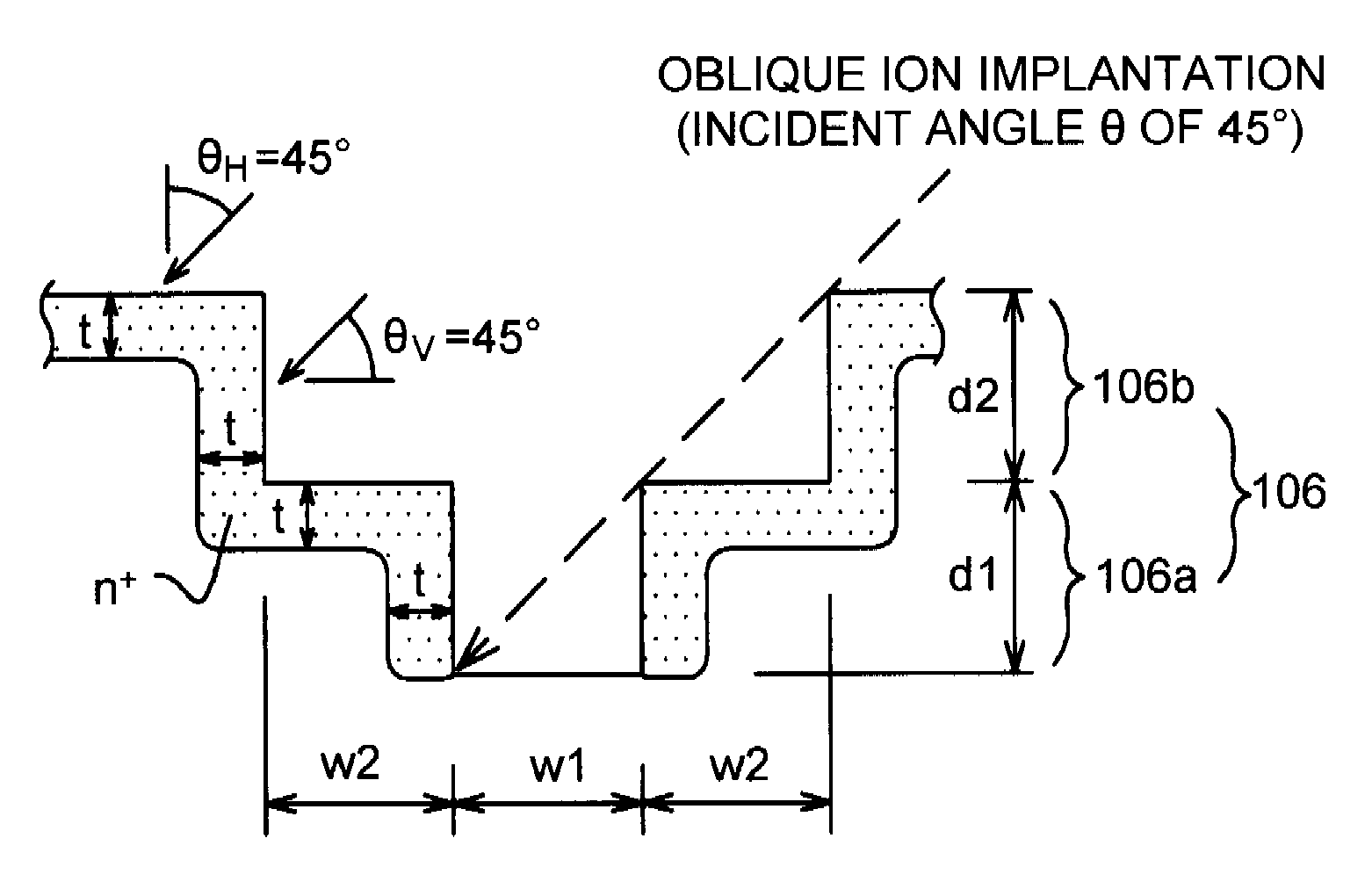
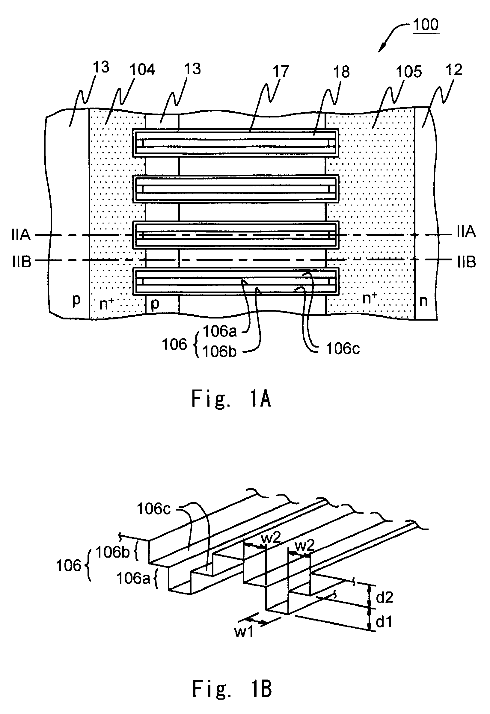
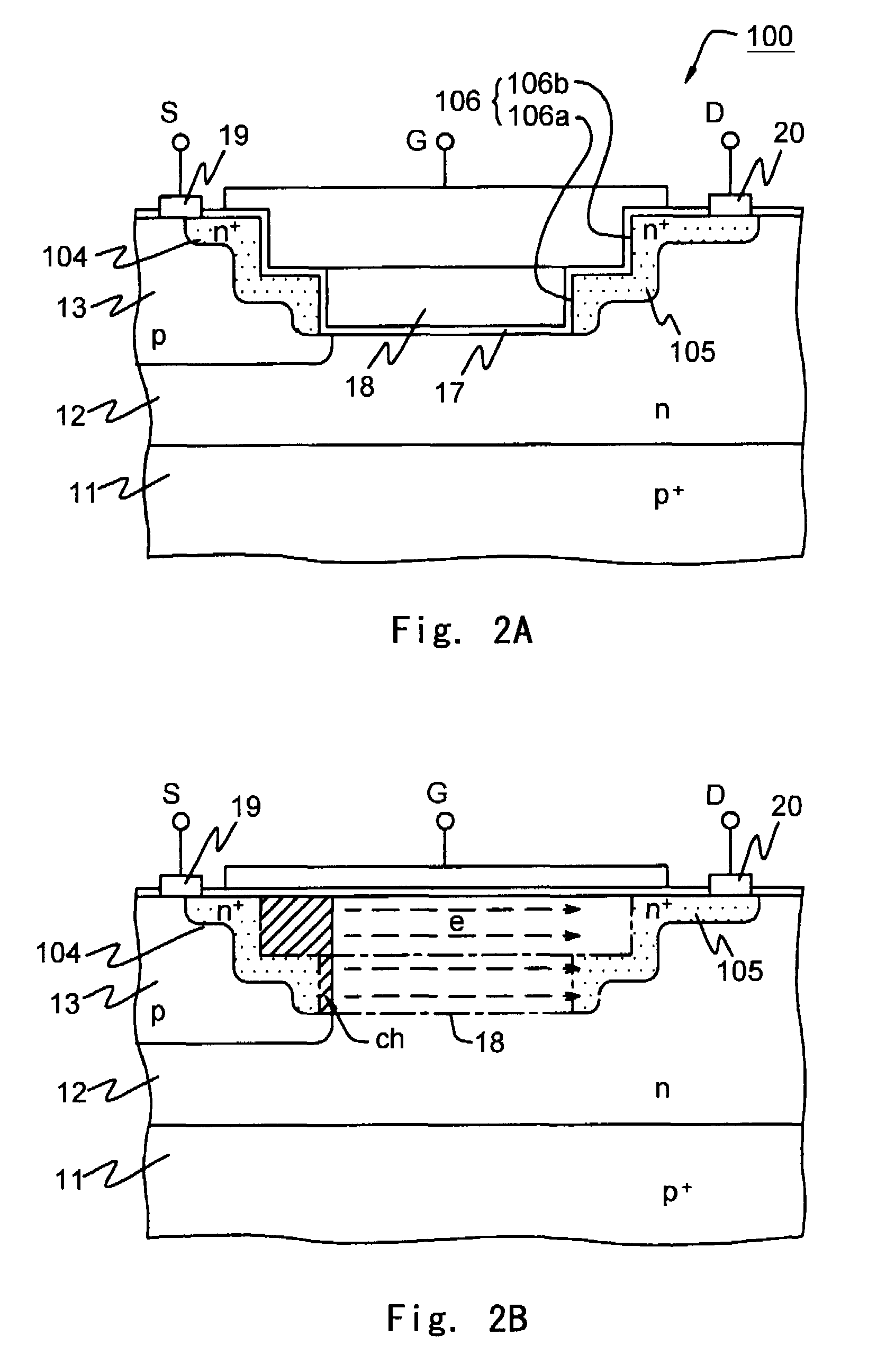
[0050]FIG. 1A is a plan view and FIG. 1B is a perspective view showing a trench shape. FIG. 2A is a cross sectional view taken along the line IIA-IIA in FIG. 1A. FIG. 2B is a cross sectional view taken along the line IIB-IIB in FIG. 1A. FIG. 4 is a cross sectional view of the trench portion. FIG. 1A does not include a surface electrode.

[0051]In FIGS. 1A, 1B, 2A, and 2B, the lateral MOSFET 100 has a p-type substrate 11, an n-type high-resistance layer 12, a p-type well layer 13, an n-type source layer 104, an n-type drain layer 105, a trench 106, a lower trench 106a, an upper trench 106b, 106c is a step surface, a gate insulation film 17, a gate electrode 18, a source electrode 19, and a drain electrode 20. Here, w1 is a lower trench widt...


PUM


Abstract

A lateral MOSFET according to the present invention has a trench gate structure having a cross sectional shape spreading toward an open end. The cross sectional shape is T-shape. The T-shaped cross section has a dimensional ratio of a width of a lower trench having a narrow width to a width of an upper trench having a wide width of 1:3, and a dimensional ratio of a depth of the lower trench to a depth of the upper trench of 1:1, the lower trench width having a same central axis as the upper trench width.

Description

BACKGROUND OF THE INVENTION[0001]1. Field of the Invention[0002]The present invention relates to a lateral MOSFET having a trench gate structure and a manufacturing method thereof.[0003]2. Description of Related Art[0004]There is proposed a lateral MOSFET having a trench gate structure as a structure to lower ON resistance by increasing a channel width without increasing an area of an element.[0005]A structure of one example of the lateral MOSFET having a prototype trench gate structure is shown in FIGS. 7A, 7B, 8A, and 8B.[0006]FIG. 7A is a plan view, and FIG. 7B is a perspective view showing a shape of a trench. FIG. 8A is a cross sectional view taken along the line IIXA-IIXA in FIG. 7A. FIG. 8B is a cross sectional view taken along the line IIXB-IIXB in FIG. 7A. FIG. 7A does not include a surface electrode.[0007]In FIGS. 7A, 7B, 8A, and 8B, a prototype lateral MOSFET 10 has a p-type substrate 11, an n-type high-resistance layer 12, a p-type well layer 13, an n-type source layer 1...

Claims


Application Information

Patent Timeline
Patent Type & Authority Patents(United States)
IPC IPC(8): H01L29/78H01L21/336
CPCH01L21/26586H01L29/4236H01L29/66704H01L29/7824H01L29/7825H01L29/0869H01L29/0886H01L29/66795
Inventor TAMURA, JUN
Owner RENESAS ELECTRONICS CORP
Why Eureka
Try Eureka