Brake lining wear sensor

a technology of wear sensor and brake caliper, which is applied in the direction of instruments, analogue processes for specific applications, force/torque/work measurement apparatus, etc., can solve the problems of readjustment of sensor, complex separation of sensor from brake caliper in order to service the brake or replace the lining, and inability to contact, etc., to achieve easy maintenance, precise and reliable measurement

Active Publication Date: 2010-10-05
PREH GMBH
View PDF12 Cites 6 Cited by
  • Summary
  • Abstract
  • Description
  • Claims
  • Application Information

AI Technical Summary

Benefits of technology

[0009]It is thus an object of the present invention to provide a device for measuring the wear-induced displacement of a brake lining relative to an associated brake caliper which is relatively economical, is easy to maintain, and permits a relatively precise and reliable measurement.
[0010]The inventive device for measuring the wear-induced displacement of a brake lining with respect to an associated brake caliper can be comprised of a transmission for translating the wear-induced displacement into a rotary motion. The conversion of this generally linear, but above all small, relative displacement or motion between the lining and caliper into a rotary motion, makes possible a more precise detection by the sensor that is also provided in accordance with the invention. One reason for this is that a rotary motion is easier to detect, and another reason is that the reduction ratio can be or is easily adjusted such that the comparatively small linear motion is associated with a comparatively large rotary excursion. For contactless communication of the rotary motion to the sensor, a contactless coupling, for example a clutch based on magnetic forces, is provided. For example, the coupling can be achieved by an electromagnetic field acting on the sensor whose change based on the lining displacement is detected by the sensor, for example by means of the Hall principle. This achieves the result that no mechanical connection is needed between the sensor and the means for producing the rotary motion. This makes maintenance easier, since there is no need for mechanical separation of this connection. For example, the sensor is arranged in a housing detachably connected to the brake caliper, and the contactless coupling occurs in the transition region between this housing and the brake caliper. Because of the contactless coupling, there is no need for any mechanical connecting means, such as clutches, and no need to provide openings for this purpose in the brake caliper or its housing or in the housing of the sensor. This makes maintenance easier. Moreover, a sensor can easily be retrofitted. Furthermore, the housing of the brake caliper is not weakened or subjected to dirt accumulation on account of the opening that otherwise would be provided. In addition, the sensor can thus be removed from the brake caliper nearly “remainder-free,” which is to say without openings remaining in the caliper, as needed.
[0011]Moreover, the device is designed according to the invention such that the sensor generates an analog or pulse-width modulated detection signal for determining the wear-induced displacement of the brake lining, wherein said signal corresponds to the particular position produced by the rotary motion. Maintenance work is made a great deal easier by the use of a pulse-width modulated signal, in particular an analog signal. Another result is that the sensor is easy to adjust, economical to produce, and especially reliable. One reason for this is that there is no need for another calibration process following a temporary power failure or disruptive power fluctuation, such as is generally necessary in the case of digital detection. Advantageously the device is designed such that only one sensor is required to detect the displacement, with the result that the device can be produced economically.

Problems solved by technology

A disadvantage in this system is that the communication is not “contactless,” which is to say that the motion is communicated directly to the potentiometer by mechanical coupling.
This mechanical coupling has the result that separating the sensor from the brake caliper in order to service the brake or replace a lining is very complicated, if it is possible at all, and may require readjustment of the sensor.
In this context, the practitioner of the art encounters the problem that the limited range of measurement of a potentiometer or Hall sensor makes detection very difficult or impossible.
Since no detection signal is produced that unambiguously corresponds to the relevant position resulting from the rotary motion, relatively complicated analysis logic is necessary, and complicated readjustment is required during maintenance, in particular after brake lining replacement.

Method used


Image

  • Brake lining wear sensor
  • Brake lining wear sensor
  • Brake lining wear sensor

Examples


Embodiment Construction

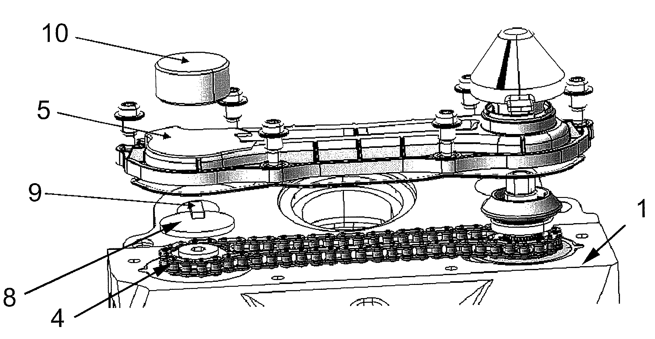
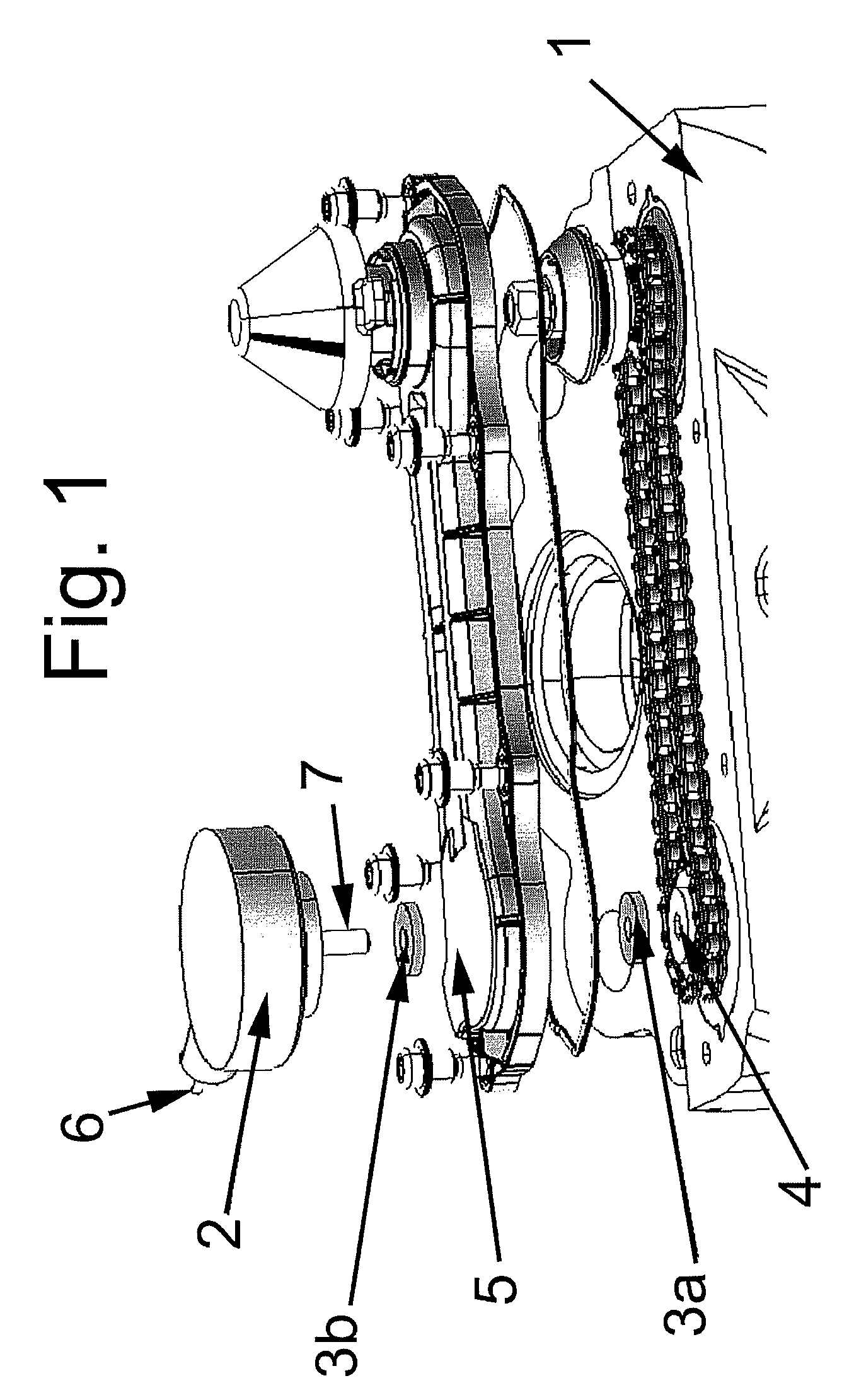
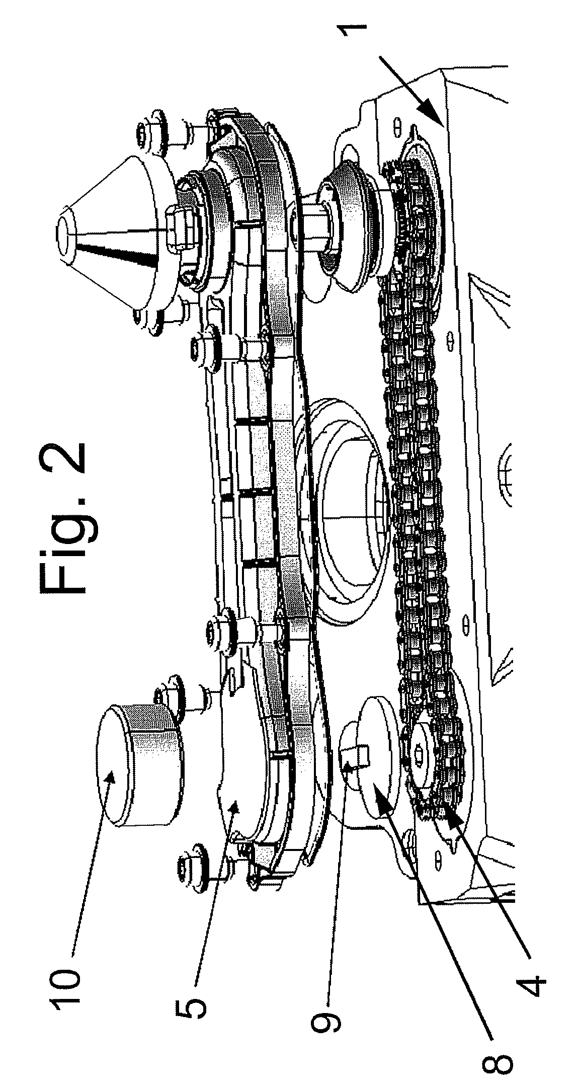
[0028]FIG. 1 shows a brake caliper 1 with a mechanical adjuster shown thereon, which also can be implemented as an electromechanical adjuster, having a transmission 4 including a chain and pinions to compensate the brake lining wear. The brake lining and the associated actuation cylinder are not shown for reasons of clarity. The transmission 4 comprises a shaft shown in the vicinity of the arrow 4, which shaft moves relative to the brake caliper proportionally to the wear-induced displacement. This rotation is communicated to a sensor 2, for which purpose a contactless coupling is provided, including a pair of magnets 3a, 3b. The transmitter magnet 3a is attached to the shaft and its magnetic force acts, through the housing 5 of the brake caliper or the adjuster, on a receiver magnet 3b located outside the housing 5, which in turn is attached to a rotatable shaft 7. The magnetic clutch consisting of the magnets 3a and 3b is responsible for communicating the rotation of the shaft 4 o...


PUM

PropertyMeasurementUnit
wear-induced displacementaaaaaaaaaa
displacementaaaaaaaaaa
magnetic forcesaaaaaaaaaa

Abstract

An apparatus is provided for measuring wear-induced displacement of a brake lining with respect to an associated brake caliper, comprising a gear mechanism for converting the wear-induced displacement into a rotary movement, having a sensor for detecting the rotary movement, wherein a contact-free coupling is provided for transmitting the rotary movement to the sensor. The apparatus is designed in such a way that the sensor generates an analogue or pulse-width-modulated detection signal for determining the wear-induced displacement of the brake lining, wherein the detection signal corresponds to the respective displacement caused by the rotary movement. The invention also related to a corresponding method for measuring the wear-induced displacement of a brake lining with respect to an associated brake caliper.

Description

[0001]This nonprovisional application is a continuation of International Application No. PCT / EP2007 / 004975, which was filed on Jun. 5, 2007, and which claims priority to German Patent Application Nos. DE 10 2006 026 833.4 which was filed in Germany on Jun. 7, 2006 and DE10 2007 026 463.3, which was filed in Germany on Jun. 5, 2007, and which are both herein incorporated by reference.BACKGROUND OF THE INVENTION[0002]1. Field of the Invention[0003]The invention relates to a sensor for contactless detection of wear in a brake lining of a motor vehicle, wherein the wear-induced displacement of the brake lining relative to the brake caliper or the displacement range of a mechanical or electromechanical adjuster for compensating the brake lining wear is determined for a subsequent electronic analysis device and / or warning device.[0004]2. Description of the Background Art[0005]Such systems are known. Thus, DE 101 32 968 A1 discloses a potentiometer with a straight-line resistive track in w...

Claims


Application Information

Patent Timeline
Patent Type & Authority Patents(United States)
IPC IPC(8): B60Q1/00G01L5/28
CPCF16D66/025F16D66/026F16D66/028
Inventor SCHMITT, HANS-MICHAELBLAUFUSS, MARTINKNUETTEL, BERNHARD
Owner PREH GMBH
Why Eureka
Try Eureka