Gas operated firearm action delay device

a delay device and firearm technology, applied in the direction of weapons, ammunition loading, firing/trigger mechanism, etc., can solve the problems of sacrificing accuracy, pistons adding weight to the rifle, and delay devices of semi-automatic rifles being required by mechanical systems, etc., to achieve increased accuracy and high fire rate

Inactive Publication Date: 2010-10-12
MONROE CHRISTOPHER ALAN
View PDF19 Cites 15 Cited by
  • Summary
  • Abstract
  • Description
  • Claims
  • Application Information

AI Technical Summary

Benefits of technology

[0012]It is an object of the present invention to overcome the drawbacks and shortcomings of conventional delay devices for semi-automatic rifles. This present invention provides for the increased accuracy while maintaining a high rate of fire.
[0013]The present invention provides the capability to delay the action of semi-automatic rifle by capturing the expanding gases created by the detonation of the round.
[0015]Further, the present invention reduces the weight of conventional delayed action semi-automatic rifles by eliminating the need for heavy mechanical mechanisms such as springs or pistons.
[0016]Additionally, the present invention increases the reliability of delayed action semi-automatic rifles by having fewer moving parts that require extensive cleaning and maintenance.

Problems solved by technology

The action of a semi-automatic rifle allows the shooter to maintain both hands on the rifle, but accuracy is sacrificed due to the movement of internal mechanisms that make-up the automation prior to the bullet leaving the barrel.
A deficiency with conventional delay devices of semi-automatic rifles is the requirement of the mechanical systems.
These mechanical systems, the springs and or pistons add weight to the rifle.
This added weight makes aiming the rifle harder, thereby reducing accuracy.
Still another deficiency with conventional delay devices is that the mechanical systems require extensive cleaning to remove the carbon build up.
Without the cleaning, the smooth operation required of the springs and pistons is compromised and the device can more readily jam.
Additionally, springs and pistons of conventional delay devices have a fatigue life expectancy and must be replaced to keep the rifle operating properly.

Method used


Image

  • Gas operated firearm action delay device
  • Gas operated firearm action delay device
  • Gas operated firearm action delay device

Examples


Embodiment Construction

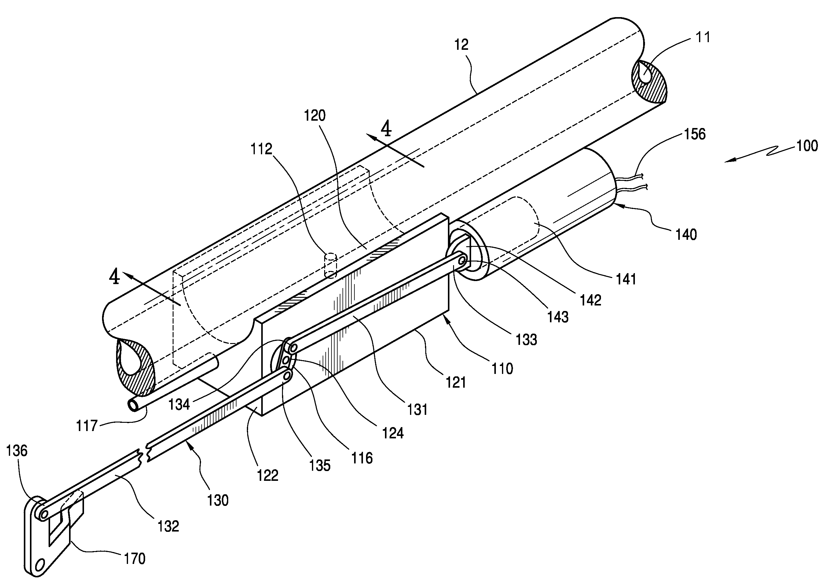
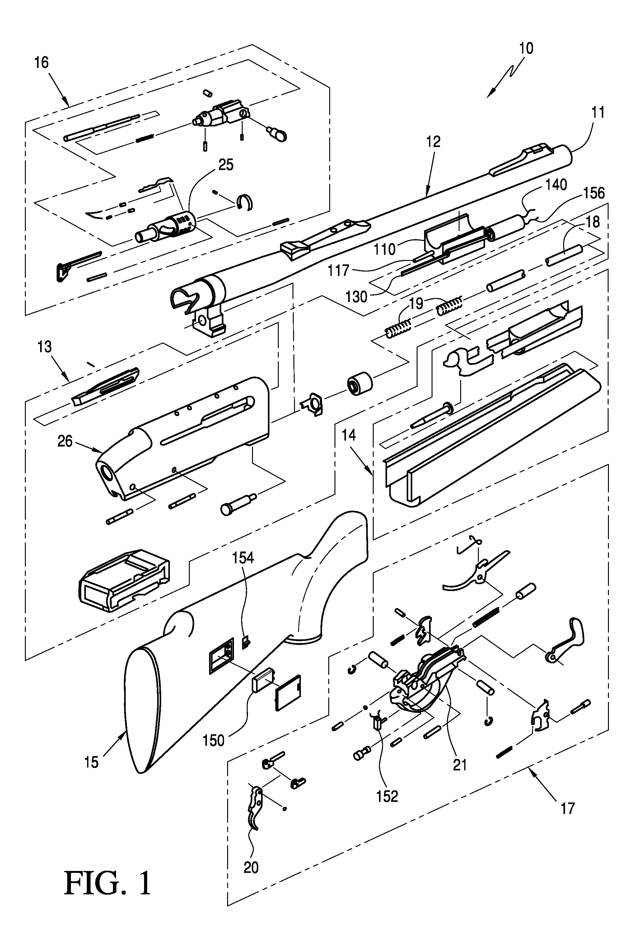
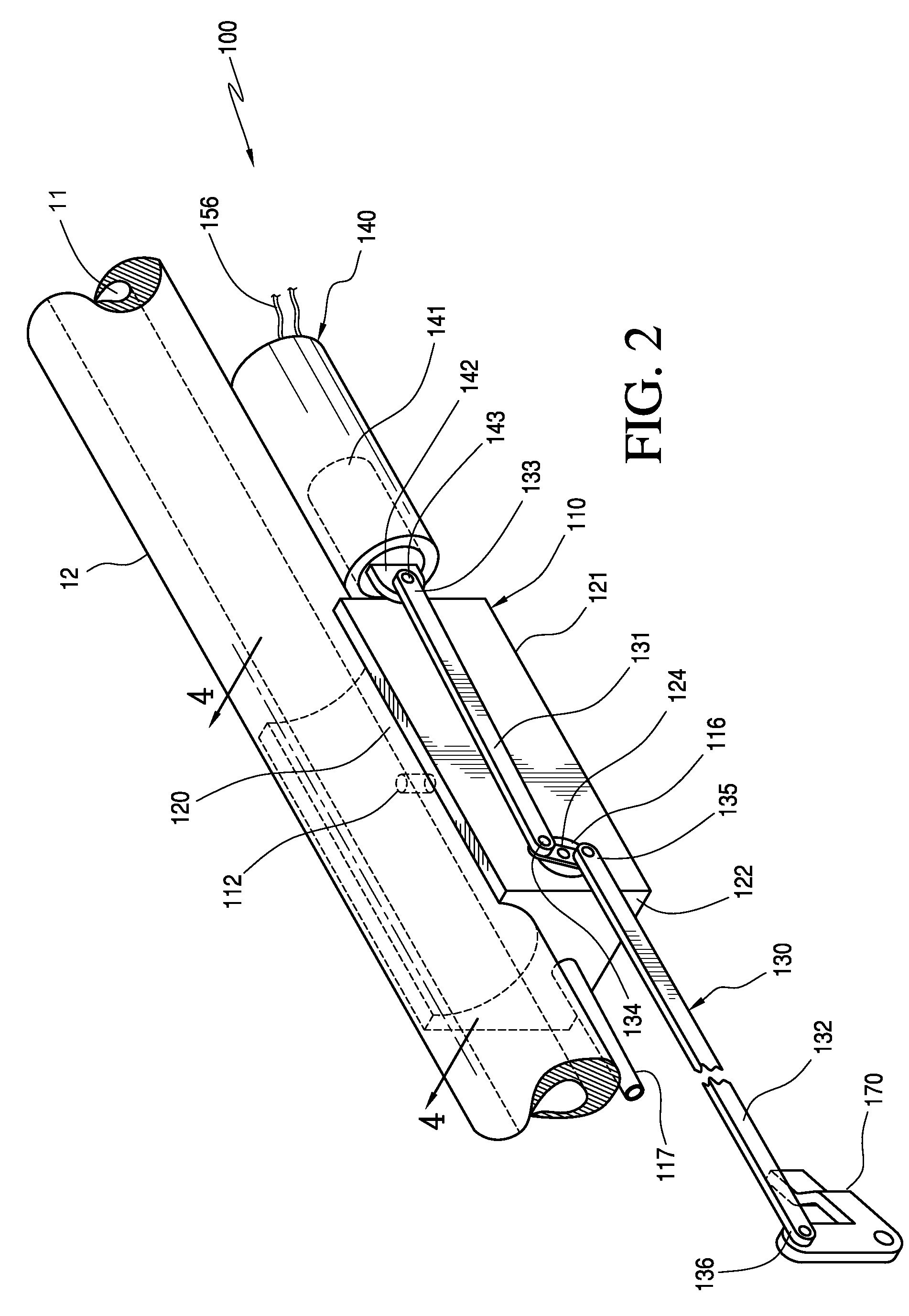
[0036]FIG. 1 is an exploded perspective view of a gas operated delay action rifle 10, made in accordance with the present invention. FIG. 2 is a detail view of action delay assembly 100 of the rifle 10, made in accordance with the present invention. FIG. 3 is a conventional gas operated action semi-automatic rifle 1 detailing common components. The conventional gas operated semi-automatic rifle 1 of FIG. 3 comprises items common to most semi-automatic rifles, such as a barrel 2, a receiver assembly 3, a fore-end assembly 4, and a stock 5. Other items common to conventional semi-automatic rifles are a breach bolt assembly 6, an action port tube 8 and an action spring 9 disposed within the receiver assembly 3. Further, the conventional rifle 1 in FIG. 1 includes a trigger assembly 7. When a shooter fires the conventional rifle 1 shown in FIG. 3, the rapidly expanding gases created by the ignition of gun powder in a cartridge pushes a bullet out of the barrel 2. The gases also are port...


PUM


Abstract

The invention relates to a device for delaying the gas action operated firearm. The device includes a gas chamber and an outlet, wherein the outlet is in fluid communication with the action tube of the firearm. The device has a port in fluid communication between the gas chamber and the barrel and a one-way check valve in the port. A gas release valve is included and is disposed on the container and in fluid communication with the gas chamber and the outlet. The device further includes linkage attached to the gas release valve and in mechanical communication with the bolt, such that when the gas release valve is in the closed position, gas is retained in the gas chamber and the linkage blocks the bolt from moving, and when the gas release valve is in the open position the linkage unblocks the bolt permitting normal gas action of the firearm.

Description

BACKGROUND OF THE INVENTION[0001]1. Field of Invention[0002]The present invention is related to the field of gas action operated firearms, and gas action operated rifles in particular.[0003]2. Description of Related Art[0004]In the use of firearms, accuracy and the rate of fire are highly valued qualities in a rifle. In general, to increase the accuracy of a rifle, the rate of fire is generally reduced. A key to increasing accuracy is to reduce the movement of the rifle during the firing of the weapon.[0005]The most accurate rifles today are bolt action rifles. Bolt action rifles fire only one round or cartridge at a time. The bolt locks a cartridge or round into the chamber of the rifle and the only movement after firing the cartridge is the motion of the bullet down the barrel and the subsequent recoil. A shooter must now manually reload the rifle. This manual reload of bolt action rifles, while accurate, reduces the rate at which they can fire.[0006]After a bolt action rifle is f...

Claims


Application Information

Patent Timeline
Patent Type & Authority Patents(United States)
IPC IPC(8): F41A9/00
CPCF41A3/62F41A5/26
Inventor MONROE, CHRISTOPHER ALAN
Owner MONROE CHRISTOPHER ALAN
Why Eureka
Try Eureka