Simultaneous pipe cutting, chamfering and grooving device

Inactive Publication Date: 2010-10-12
KAROW PHILIP
View PDF17 Cites 22 Cited by
  • Summary
  • Abstract
  • Description
  • Claims
  • Application Information

AI Technical Summary

Benefits of technology

[0007]It is an object of this invention to provide a cutting/chamfering/grooving device that is able to cut/ch

Problems solved by technology

The devices of the prior art have, however, a number of problems and shortcomings.
They often are not mobile and do not have the ability to field-cut pipe, chamfer the cut ends and groove the pipe all in one step.
The devices in the prior art cannot add a groove to the pipe body unless it is manually done in an additional step with an abrasive cut-off saw.
In addition, most cutting/chamfering/grooving devices of the prior art achieve a cut, bevel and groove that is inhere

Method used


Image

  • Simultaneous pipe cutting, chamfering and grooving device
  • Simultaneous pipe cutting, chamfering and grooving device
  • Simultaneous pipe cutting, chamfering and grooving device

Examples


Embodiment Construction

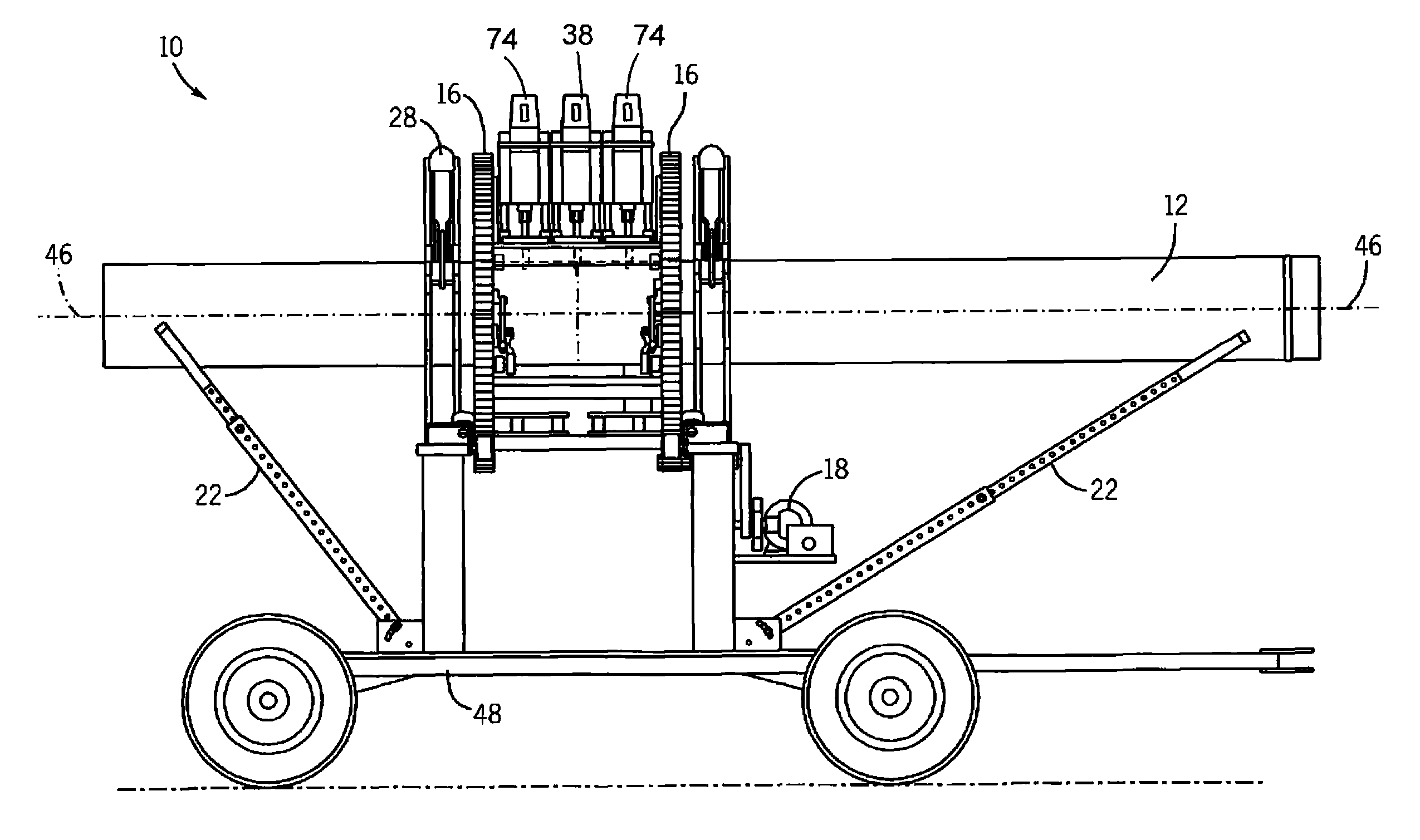
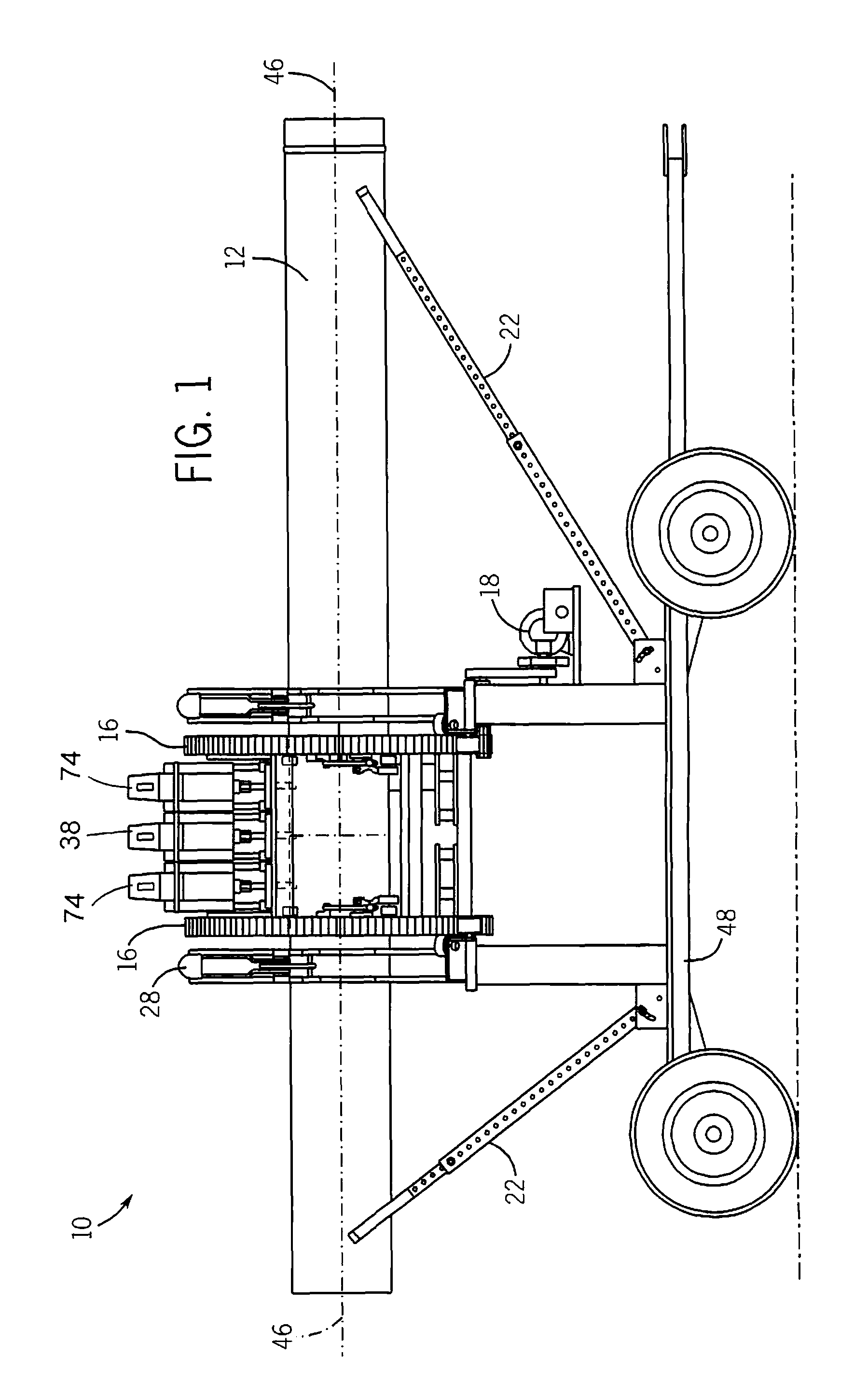
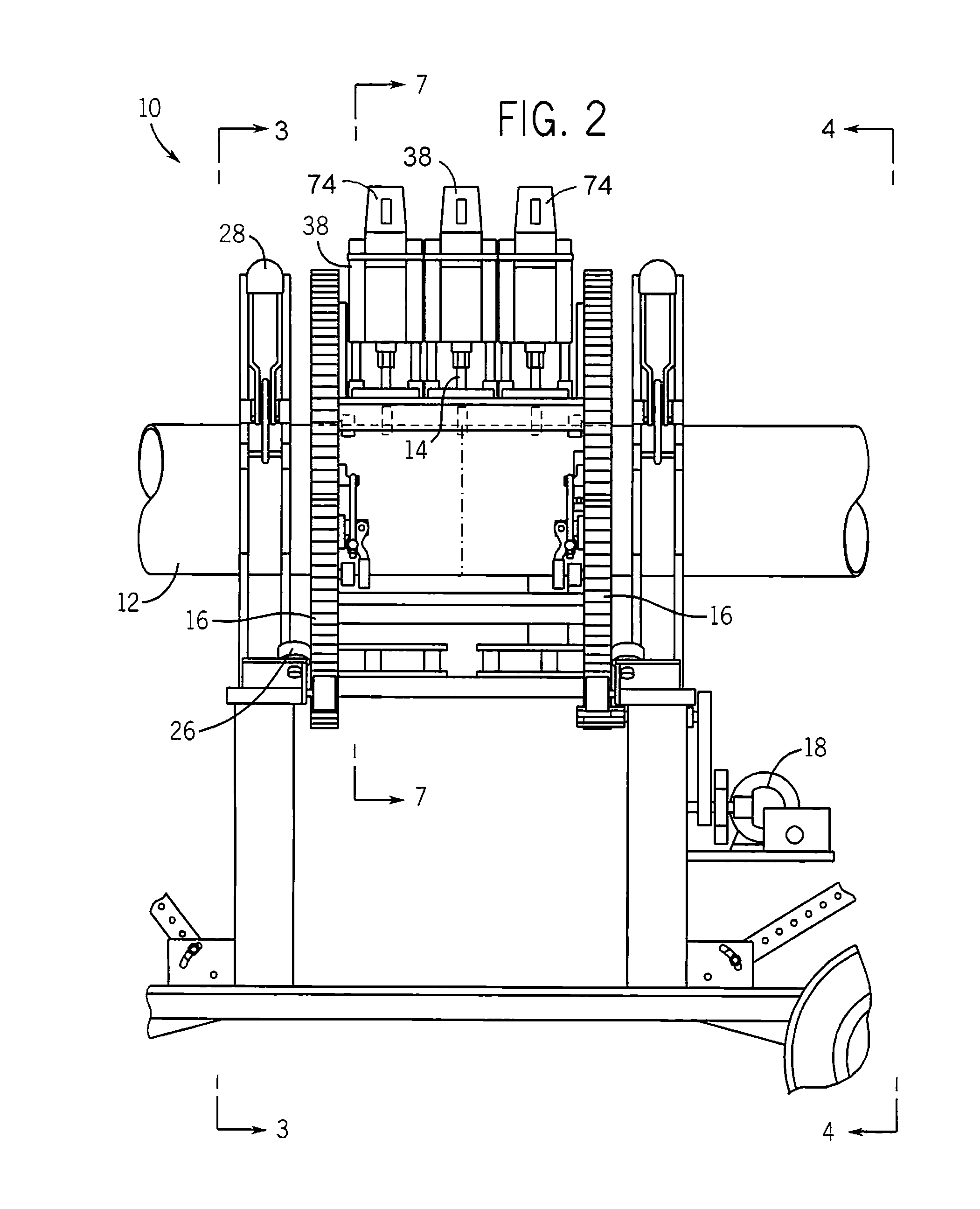
[0041]FIGS. 1-14 illustrate a mobile device 10 for simultaneously cutting, chamfering and grooving a pipe 12 including a frame 48, at least one pipe collet-clamp 28 attached to the frame 48 and defining a principal axis 46, a split carriage 16 rotatably mounted with respect to the frame 48 about the axis 46 and adjacent to the clamp(s) 28, a router 38 affixed to the split carriage 16 and having a cutting-chamfering bit 14, a grooving router 74 for grooving pipe affixed to the frame 48 and a drive motor 18 for rotating carriage 16. As illustrated in FIGS. 1-4 and 13, router 38 and grooving router 74 orbit around pipe 12 simultaneously cutting it into two chamfered and grooved pipes 12.

[0042]FIGS. 1-4, 7, 11 and 13-14 illustrate that pipe-cutting / chamfering / grooving device 10 is the combination of the traveling carriage 16 which travels around pipe 12 and a custom-designed bit 14 (illustrated in FIG. 10(a)) which simultaneously cuts pipe 12 and chamfers both cut ends quickly and accur...


PUM

PropertyMeasurementUnit
Angleaaaaaaaaaa
Forceaaaaaaaaaa
Sizeaaaaaaaaaa

Abstract

A mobile device for simultaneously cutting, chamfering and grooving a pipe. The device having a frame, at least one pipe collet-clamp attached to the frame and defining a principal axis, a split carriage rotatably mounted with respect to the frame about the axis and adjacent to the clamp(s), a router affixed to the split carriage and having a cutting-chamfering bit, a grooving router and a drive motor for rotating the carriage. The routers orbit around the pipe and simultaneously cuts the pipe into two chamfered pipes with grooves. A method is also provided for cutting through a pipe, chamfering the cut ends thereof and grooving the pipe.

Description

FIELD OF THE INVENTION[0001]This invention is related generally to devices for cutting, chamfering and grooving pipe and more particularly to devices that are mobile and can simultaneously cut through a pipe, chamfer the cut ends and cut a groove into the pipe.BACKGROUND OF THE INVENTION[0002]Devices which cut and chamfer pipe are used in numerous operations which require pipe to be cut to certain lengths and which also require the pipe after cutting to have a factory-like chamfer on the pipe ends. Such operations also may require that a pipe have grooves cut into the body of the pipe. Such cutting / chamfering / grooving devices in the prior art typically consist of a driving motor with a saw blade that is manually guided around the pipe to cut the pipe to the desired length. The pipe is then chamfered with a milling cutter in an additional process after it has been cut. If a groove is needed the pipe is manually cut with router, saw or rotary cutter to add a groove on the pipe body. T...

Claims


Application Information

Patent Timeline
IPC IPC(8): B23C3/34B23B5/16
CPCB23C3/007B23C3/02B23C3/34B23D21/006B23D21/04Y10T82/2529Y10T29/5199Y10T409/30644Y10T409/304144Y10T409/307616Y10T82/22Y10T409/307168
Inventor KAROW, PHILIP
Owner KAROW PHILIP
Why Eureka
Try Eureka