Adjustable kettlebell

a kettlebell and adjustable technology, applied in the field of adjustable kettlebells, can solve the problems of not being able to easily adjust or adjust the weight of the typical adjustable kettlebell may not be easily operated by users, and the weight of the typical adjustable kettlebell may not be easily adjusted or adjusted. achieve the effect of improving the structure, easy and quickly and easily attached to or disengaged weight members

Inactive Publication Date: 2010-10-12
CHEN PAUL
View PDF11 Cites 26 Cited by
  • Summary
  • Abstract
  • Description
  • Claims
  • Application Information

AI Technical Summary

Benefits of technology

[0010]The primary objective of the present invention is to provide an adjustable kettlebell or exercise device including an improved structure for allowing the weight members to be easily and quickly and adjustably attached to or disengaged from the weight carrier and for allowing the adjustable kettlebell to be easily operated by the users.
[0011]In accordance with one aspect of the invention, there is provided an adjustable kettlebell comprising a shaft including a first end portion, and including a second end portion, and including a narrowed neck segment formed in the first end portion of the shaft, a base plate attached to the second end portion of the shaft and including an outer diameter greater than that of the shaft, a first weight member and at least one second weight member each including a slot formed therein and having a width no less than the narrowed neck segment of the shaft for receiving the narrowed neck segment of the shaft, and for allowing the first and the second weight members to be attached to and disengaged from the shaft, the first and the second weight members each including an enlarged opening formed therein and communicating with the slot of the first and the second weight member, and the enlarged opening including an inner diameter greater than the width of the slots of the first and the second weight members and no less than the outer diameter of the shaft for receiving the shaft, and for allowing the first and the second weight members to be retained to the shaft and for preventing the first and the second weight members from being disengaged from the shaft when the first and the second weight members are offset from the narrowed neck segment of the shaft, and a sliding member slidably attached onto the shaft for engaging with the weight members after the weight members have been engaged onto the shaft and after the weight members have been disengaged from the narrowed neck segment of the shaft, and the sliding member including a latch for engaging with the shaft and for selectively and quickly or easily locking or latching the sliding member to the shaft, in order to retain and secure the weight members to the shaft.
[0016]The weight members each include an open end communicating with the slots of the weight members for guiding the narrowed neck segment of the shaft to be easily and quickly engaged into the slots of the weight members.

Problems solved by technology

However, the weight plates may not be easily adjusted and / or changeably attached to the central plate such that the weight of the typical kettlebell may not be changed or adjusted.
However, the base should be removed or disengaged from the shaft when engaging the weight plates onto the shaft or when disengaging the weight plates from the shaft, such that it takes time to attach or to disengage the weight plates from the shaft and such that the typical adjustable kettlebell may not be easily operated by the users.

Method used


Image

  • Adjustable kettlebell
  • Adjustable kettlebell
  • Adjustable kettlebell

Examples


Embodiment Construction

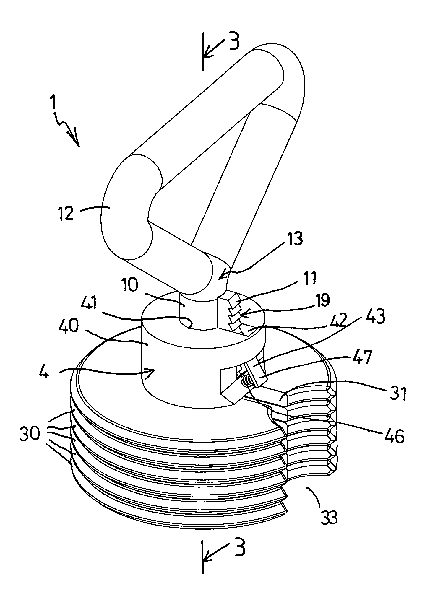
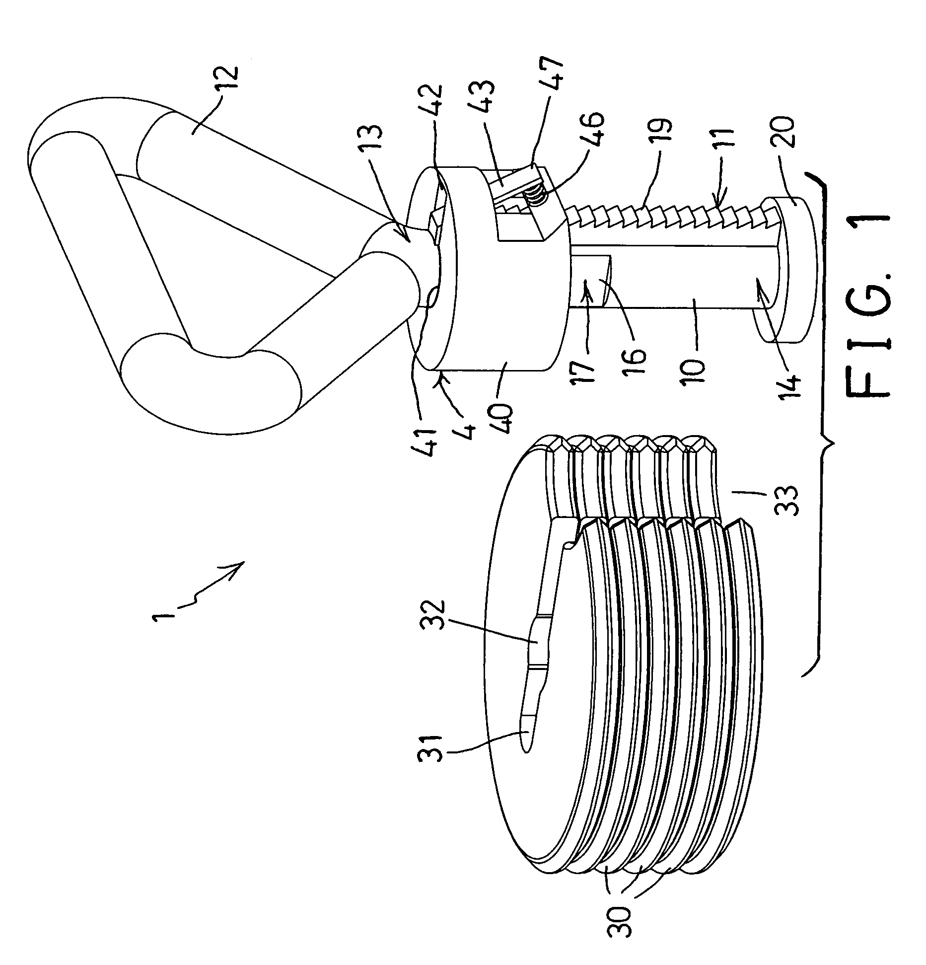
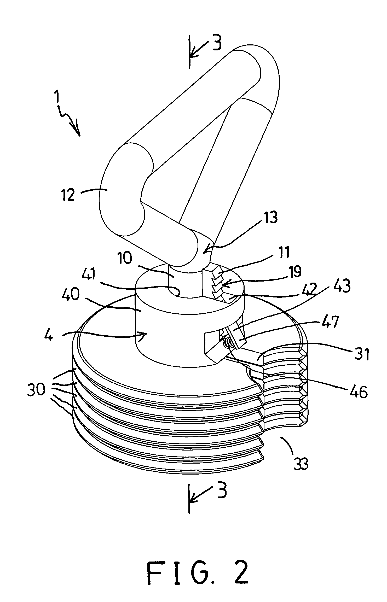
[0023]Referring to the drawings, and initially to FIGS. 1-4, an adjustable kettlebell 1 in accordance with the present invention comprises a longitudinal and / or vertical or central shaft 10 including a rack 11 formed or provided on the outer peripheral portion thereof, and including a handle 12 formed or provided on the upper portion or one end portion 13 of the shaft 10 for being grasped or held by the users and for carrying or lifting or moving the shaft 10 and for allowing the adjustable kettlebell 1 to be easily operated by the users. A carrier or base plate 20 is attached or secured to the lower or bottom portion or the other end portion 14 of the shaft 10 with one or more latches or fasteners 15, in which the base plate 20 includes an outer diameter greater than that of the shaft 10.

[0024]The base plate 20 may also be formed integral with the handle 10 with molding or mold-injection processes or with forging processes. The rack 11 is preferably extended out of the shaft 10 and...


PUM


Abstract

An adjustable kettlebell includes a shaft having a narrowed neck segment formed on one end portion and having a base plate attached to the other end portion, two or more weight members each having a slot for receiving the narrowed neck segment of the shaft, and each having an enlarged opening communicating with the slot for receiving the shaft and for retaining the weight members to the shaft when the weight members are offset from the narrowed neck segment of the shaft, and a sliding member is slidably attached onto the shaft for engaging with the weight members after the weight members have been disengaged from the narrowed neck segment of the shaft and for retaining the weight members to the shaft.

Description

BACKGROUND OF THE INVENTION[0001]1. Field of the Invention[0002]The present invention relates to an adjustable kettlebell, and more particularly to an adjustable kettlebell including an improved structure for allowing the weight members to be easily and quicly and adjustably attached to or disengaged from the weight carrier and for allowing the adjustable kettlebell to be easily operated by the users.[0003]2. Description of the Prior Art[0004]Typical kettlebells comprise a pair of oppositely-facing, generally frustum-shaped weight plates attached to a central plate with a first axis that is perpendicular to the axis of its handle, and the frustum-shaped weight plates may reduce the force of impact against the user's forearm during certain exercise movements.[0005]For example, U.S. Pat. No. 7,182,715 to Anderson discloses one of the typical kettlebells comprising a handle attached to a central plate and including places which can be held between the user's thumb and remaining fingers...

Claims


Application Information

Patent Timeline
Patent Type & Authority Patents(United States)
IPC IPC(8): A63B21/072A63B21/075
CPCA63B21/072A63B21/0728
Inventor CHEN, PAUL
Owner CHEN PAUL
Why Eureka
Try Eureka