Sensor device

a technology of sensors and sensors, applied in the direction of turn-sensitive devices, instruments, navigation instruments, etc., can solve the problems of difficult detection of the malfunction of one of the sensors, the accuracy of the sensors, and the inability to obtain information, so as to improve the traditional imu structure, simplify the structure, and improve the effect of performan

Active Publication Date: 2010-10-19
IMEGO
View PDF18 Cites 73 Cited by
  • Summary
  • Abstract
  • Description
  • Claims
  • Application Information

AI Technical Summary

Benefits of technology

[0008]As a further advantage, an additional signal giving information about the state of the IMUs is obtained. Moreover, a redundant system is obtained, which is fully functional even in the case of one gyro or one accelerometer malfunctioning—albeit at a somewhat lesser performance.

Problems solved by technology

However, no information is obtained with this configuration about the sensors' precision and it is difficult to detect the malfunction of one of the sensors malfunction.
Moreover, the system is sensitive to disturbances as the sensors cannot be coupled differentially.
This presents a more complicated arrangement and an increase in cost.

Method used


Image

  • Sensor device
  • Sensor device
  • Sensor device

Examples


Embodiment Construction

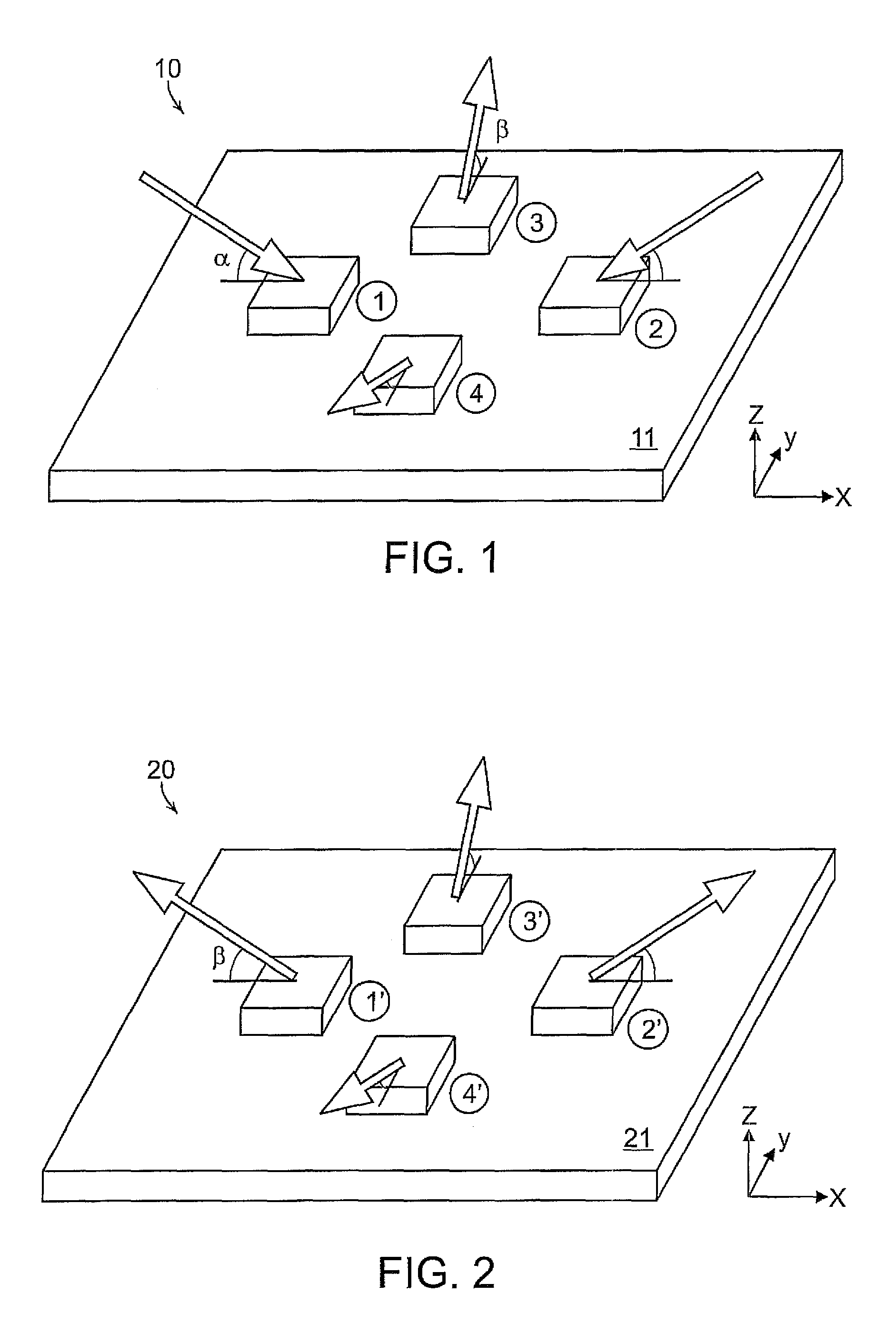
[0022]The principle for the mounting of the sensors is shown in FIG. 1 schematically showing a first embodiment of a sensor arrangement 10 with four sensors 1-4 mounted onto a substrate in the form of accelerometers or gyroscopes. In this fashion, the sensors are arranged in the form of faces of a rectangle. The sensitivity axes for the respective sensors are illustrated by arrows, where the sensitivity axes for sensors 1 and 2 are directed towards the sensors at an angle α, whereas the sensitivity axes for sensors 3 and 4 are directed outwards from the sensors at an angle β.

[0023]With the four sensors configured according to FIG. 1 the x-, y- and z-signals are obtained as:

xsignal∝1signal−2signal

ysignal∝3signal−4signal

zsignal∝1signal+2signal+3signal−4signal

0=−1signal+2signal+3signal−4signal

[0024]In the equations above, the numbers 1-4 correspond to the accelerometers or gyros 1-4.

[0025]The last equation comprises the information on the state of the measurement system, such as, f...


PUM


Abstract

The present invention is related to sensor arrangements and particularly to sensor arrangements for symmetric response in a x-, y- and z-coordinate system. The arrangement comprises four gyroscopes with one axis arranged into different directions of sensitivity.

Description

PRIORITY INFORMATION[0001]The present application is a continuation of PCT Application Serial No. PCT / SE2005 / 001570 filed on Oct. 20, 2005 that claims priority to Swedish Application Serial No. SE-0402566-4, filed on Oct. 20, 2004. Both applications are incorporated herein by reference in their entireties.TECHNICAL FIELDBackground of the Invention[0002]Traditionally, IMUs (Inertial Measurement Units) are constructed using three accelerometers and three gyros having their sensitivity direction in three orthogonal planes, for example in one perpendicular corner. However, no information is obtained with this configuration about the sensors' precision and it is difficult to detect the malfunction of one of the sensors malfunction. Moreover, the system is sensitive to disturbances as the sensors cannot be coupled differentially.[0003]U.S. Pat. No. 4,179,818 describes a redundant inertial reference system with four gyroscope units having two axes, with the spin axes of the gyroscopes in t...

Claims


Application Information

Patent Timeline
Patent Type & Authority Patents(United States)
IPC IPC(8): G01P3/44G01CG01C21/16G01P15/18
CPCG01C21/16G01P15/18G01C21/166G01C19/02G01C19/56G01C21/10
Inventor ANDERSSONRODJEGARD, HENRIK
Owner IMEGO
Why Eureka
Try Eureka