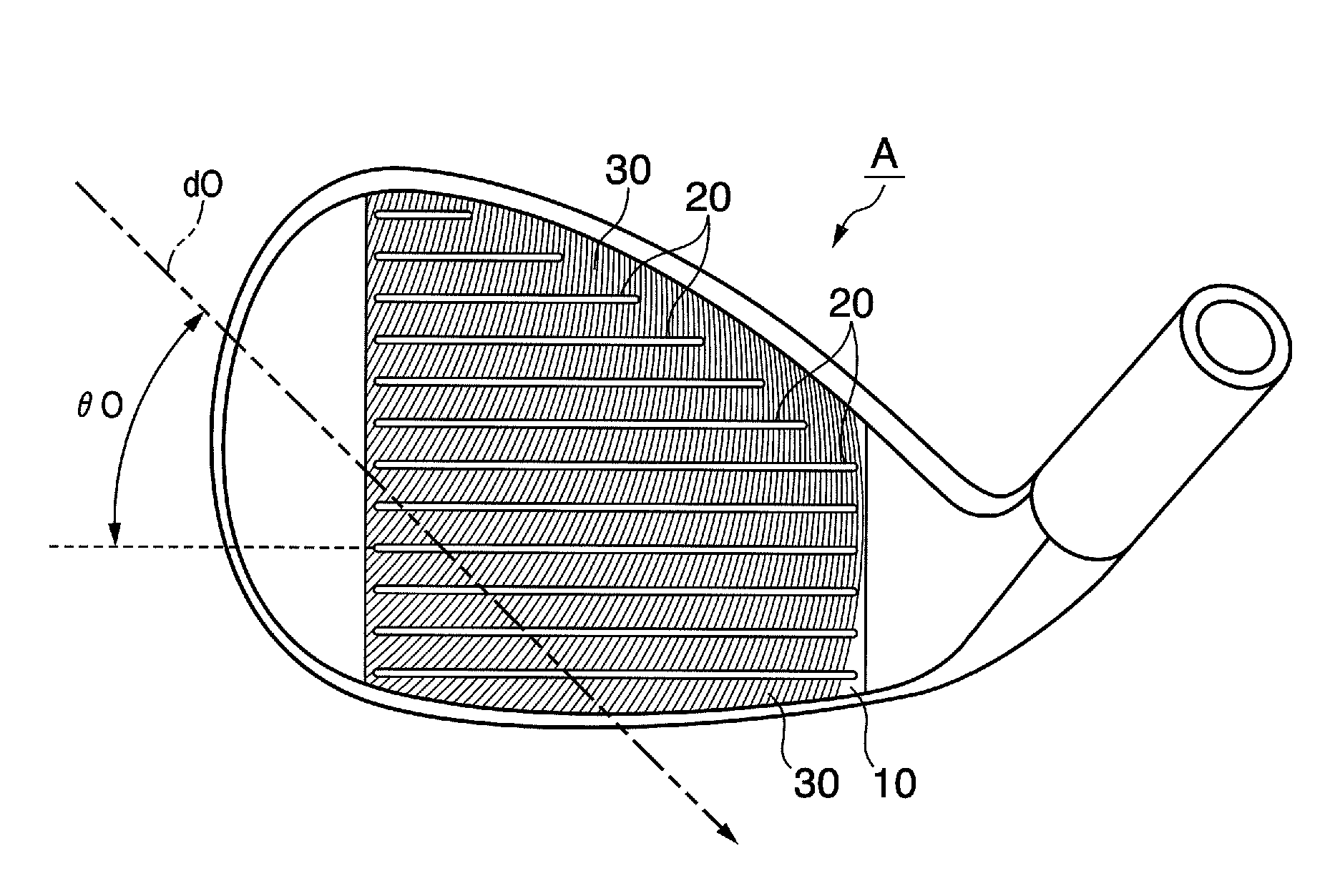
Golf club head

a golf club and head technology, applied in the field of golf club head, can solve the problems of golf club head disclosed in japanese patent laid-open, affecting the surface roughness of the face of the ball, increasing the etc., to avoid significant decline in spin, avoid damage to the ball, and avoid significant damage to the ball

Inactive Publication Date: 2010-10-19
BRIDGESTONE SPORTS
View PDF97 Cites 221 Cited by
  • Summary
  • Abstract
  • Description
  • Claims
  • Application Information

AI Technical Summary

Benefits of technology

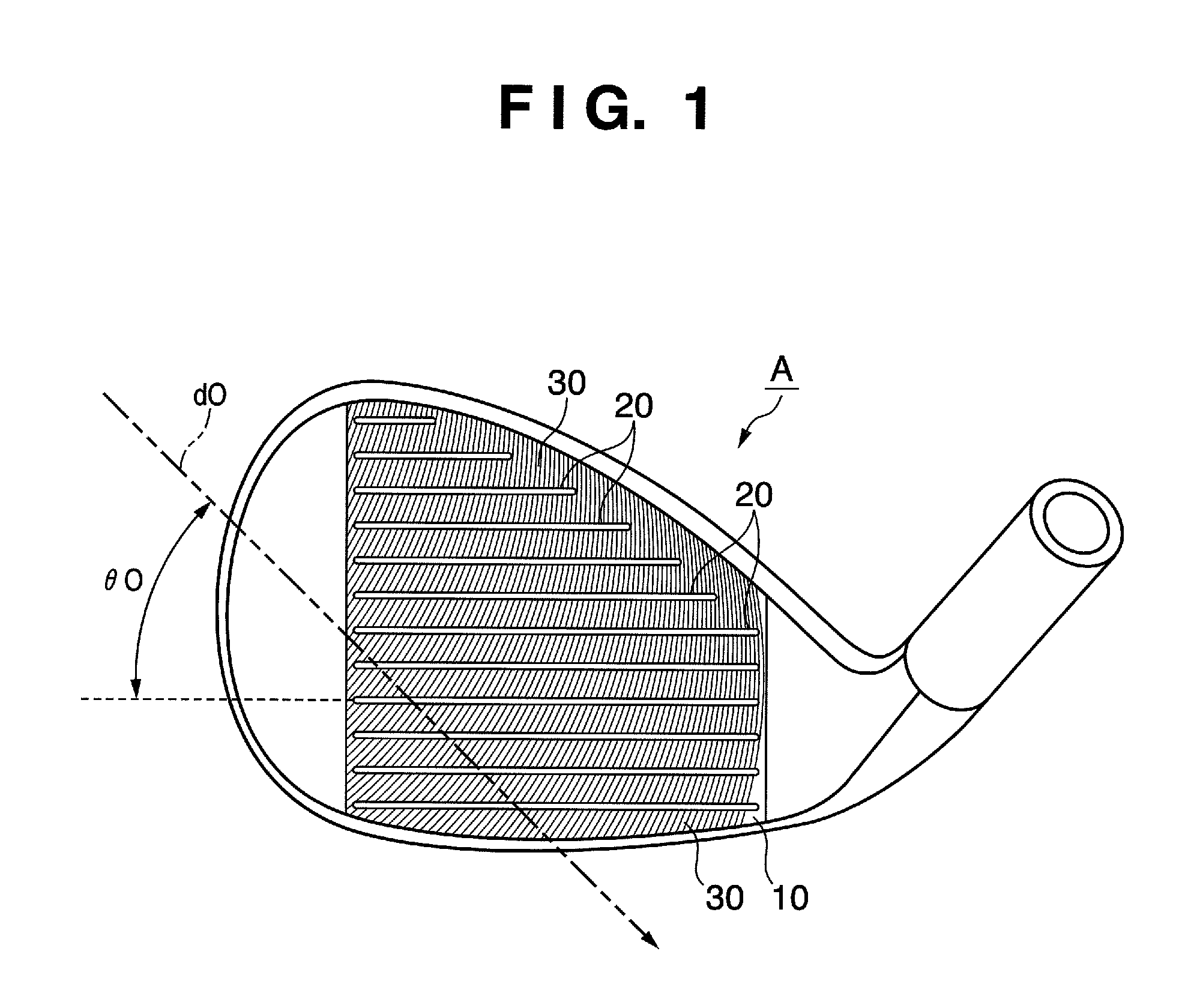
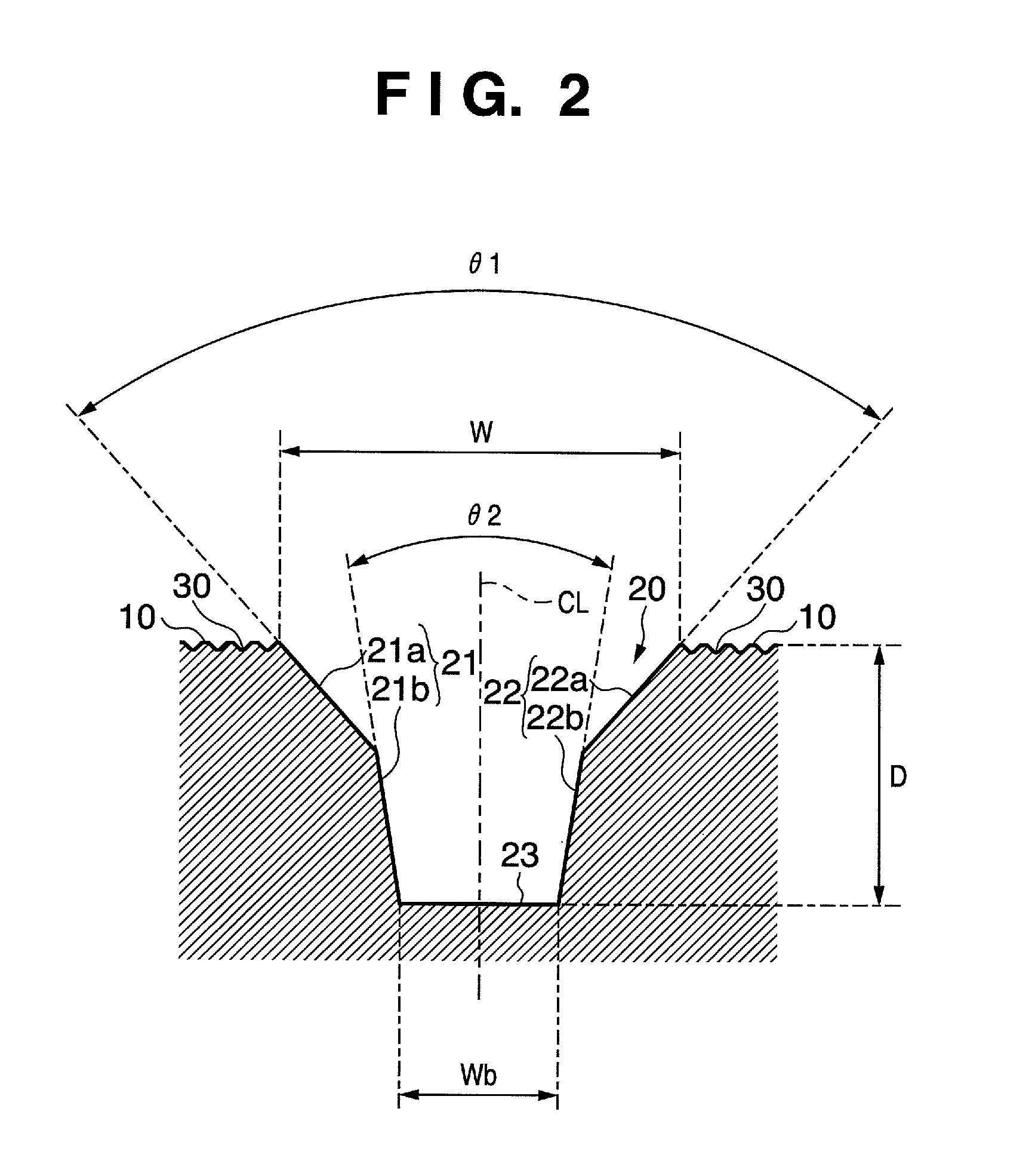
[0013]The golf club head is formed such that the first angle, which is formed by the first side, is larger than the second angle, which is formed by the second side surfaces. The first side surfaces of the score line grooves contribute to avoiding damage to the ball, and the second side surfaces contribute to ensuring volume in the score line grooves. Therefore, the golf club head can avoid significant declines in spin when hitting in bad weather or in the rough, as well as damage to the ball.
[0014]The arithmetic mean deviation of the profile (Ra) of not less than 4.00 μm in the face allows significantly greater spin through improved friction between the ball and the face.

Problems solved by technology

The amount of spin on the ball affects the surface roughness of the face as well.
Score line grooves with square cross-sectioning tends to have larger volume than score line grooves with other cross-sectioning, presuming an identical width, at the cost of increased damage to the ball, owing to a sharper angle on the edges of the score line groove.
The golf club head disclosed in Japanese Patent Laid-Open No. 2005-287534 may be unworkable, owing to the width of the interior of the score line groove being wider than the score line groove in the face.
The score line groove edges also have sharp angles that cause greater damage to the ball.
While Japanese Patent Laid-Open No. 2005-287534 discloses a golf club head with rounding on the edges of the score line groove, score line groove edges with significantly sharp angles, such as the score line grooves in Japanese Patent Laid-Open 2005-287534, may cause greater damage to the ball even if the edges are rounded.
Even if the surface roughness of the face is modified, such as with the golf club heads disclosed in Japanese Patent Laid-Open No. 2005-169129 and Japanese Patent No. 3,000,921, poor drainage performance on the face will reduce spin.

Method used


Image

  • Golf club head
  • Golf club head
  • Golf club head

Examples


example

[0099]An experiment was performed to evaluate amount of spin on the ball in comparative examples, as well as the example of the present invention. FIG. 14A depicts the specification of the example of the present invention and comparative examples 1 to 3, and FIG. 14B depicts the findings of the experiment performed on the specification of the example of the present invention and the comparative examples 1 to 3. The example of the present invention and the comparative examples 1 to 3 are all sand wedges with a loft angle of 56 degrees.

[0100]The meanings of the respective items listed under the “score line groove specifications” heading in FIG. 14A are the same as the meanings for the respective items in FIG. 10. The cross-sectional shape of the score line groove in the example and the comparative example 3 are the cross-sectional shapes depicted in FIGS. 2 and 4A. The cross-sectional shapes of the score line grooves in the comparative example 1 and the comparative example 3 are the c...


PUM


Abstract

The present invention provides a golf club head comprising, a face, a plurality of score line grooves formed in the face, traces formed in the face by milling; and a pair of side surfaces of the score line groove including a first surface that is contiguous with the face and a second surface that is contiguous with the first surface in the depth direction of the score line groove. A first angle that is formed by each first surface of the pair of side surfaces is larger than a second angle that is formed by each second surface of the pair of surfaces. The face in which the traces are formed has the arithmetic mean deviation of the profile (Ra) of not less than 4.00 μm.

Description

BACKGROUND OF THE INVENTION[0001]1. Field of the Invention[0002]The invention relates to a golf club head.[0003]2. Description of the Related Art[0004]The face of a golf club head include a plurality of grooves, known as marking lines, score lines, or face line grooves (hereinafter referred to as score line grooves), which affect the amount of spin on a ball. It is desirable to have the grooves on an iron club head, especially a wedge, in order to increase the amount of spin on the ball.[0005]Japanese Patent Application Laid-Open No. 9-192274 discloses a golf club having grooves of V-shaped or trapezoidal cross section. Japanese Patent Application Laid-Open No. 9-70457 and No. 10-179824 disclose a golf club head with rounding on the edges of the score line groove, that is, where the score line grooves meets the face. The rounding has the effect of avoiding scratching or other damage to the ball. Japanese Patent Laid-Open No. 2003-93560 and No. 2005-287534 disclose a golf club head h...

Claims


Application Information

Patent Timeline
Patent Type & Authority Patents(United States)
IPC IPC(8): A63B53/04
CPCA63B53/047A63B53/04A63B53/0466A63B2053/0408A63B2053/0445A63B53/0445A63B53/0408A63B60/00
Inventor BAN, WATARUNGUYEN, VINH-DUY THAI
Owner BRIDGESTONE SPORTS
Why Eureka
Try Eureka