
Speed sensing circuit for a wind turbine generator

a technology of speed sensing circuit and wind turbine generator, which is applied in the direction of electric generator control, machine/engine, dynamo-electric converter control, etc., can solve the problems of low efficiency inconvenient operation of mechanical braking system, and inability to optimize the operation time and thus power output of wind turbine generator,

Inactive Publication Date: 2010-10-19
INT COMPONENTS
View PDF47 Cites 10 Cited by
  • Summary
  • Abstract
  • Description
  • Claims
  • Application Information

AI Technical Summary

Benefits of technology

[0020]The present invention relates to a protection circuit for a wind turbine generator that includes a PWM Brake that works in conjunction with known Brake Relays. The Brake Relay is used to short the generator output terminals at a first threshold voltage. The PWM Brake includes one or more switching devices, coupled across the generator output. The PWM Brake is under the control of a PWM Brake Control Circuit which actuates the PWM Brake at a second threshold voltage that is relatively lower than the first threshold voltage. In accordance with an important aspect of the invention, the PWM Brake Control Circuit includes a novel speed sensing circuit for providing a signal representative of the speed of the turbine generator The novel speed sensing circuit eliminates the need to mount a speed sensor on the pole top mounted turbine generator. As such, the need for adding cabling from the pole top mounted wind turbine generator is eliminated. The novel speed sensing circuit provides a signal representative of the rotational speed of the turbine generator based upon the duty cycle of a pulse width modulated (PWM) signal that is derived from the drive signal developed by the PWM Control Circuit. This signal is used to alternatively actuate and close the Brake Relay to minimize actuation of the centrifugal switch.

Problems solved by technology

One problem with such systems is that wind speeds are not constant.
While mechanical brakes do an adequate job of protecting the wind turbine generator from over speed, mechanical braking systems do little to optimize the operational time and thus power output of the wind turbine generator.
Moreover, such mechanical braking systems are mechanically complex and are, thus, relatively expensive.
Thus, wind gusts are known to cause the generator voltage to rise high enough to trip the Brake Relay, thus causing a disruption of power delivered to the AC power grid.
As such, this condition makes wind turbine energy systems 20 less desirable as a renewable energy source.
Considering the number of wind turbine generators in a wind turbine generator farm, such cabling would substantially add to the cost of the overall wind turbine generator system.

Method used


Image

  • Speed sensing circuit for a wind turbine generator
  • Speed sensing circuit for a wind turbine generator
  • Speed sensing circuit for a wind turbine generator

Examples


Embodiment Construction

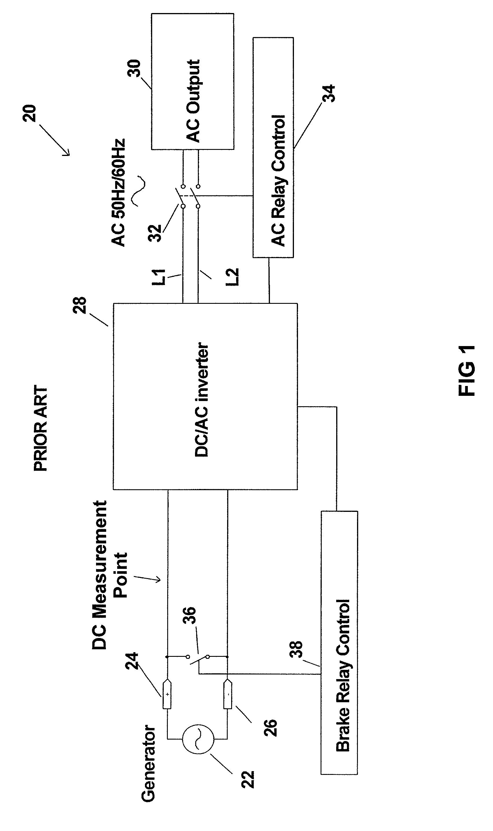
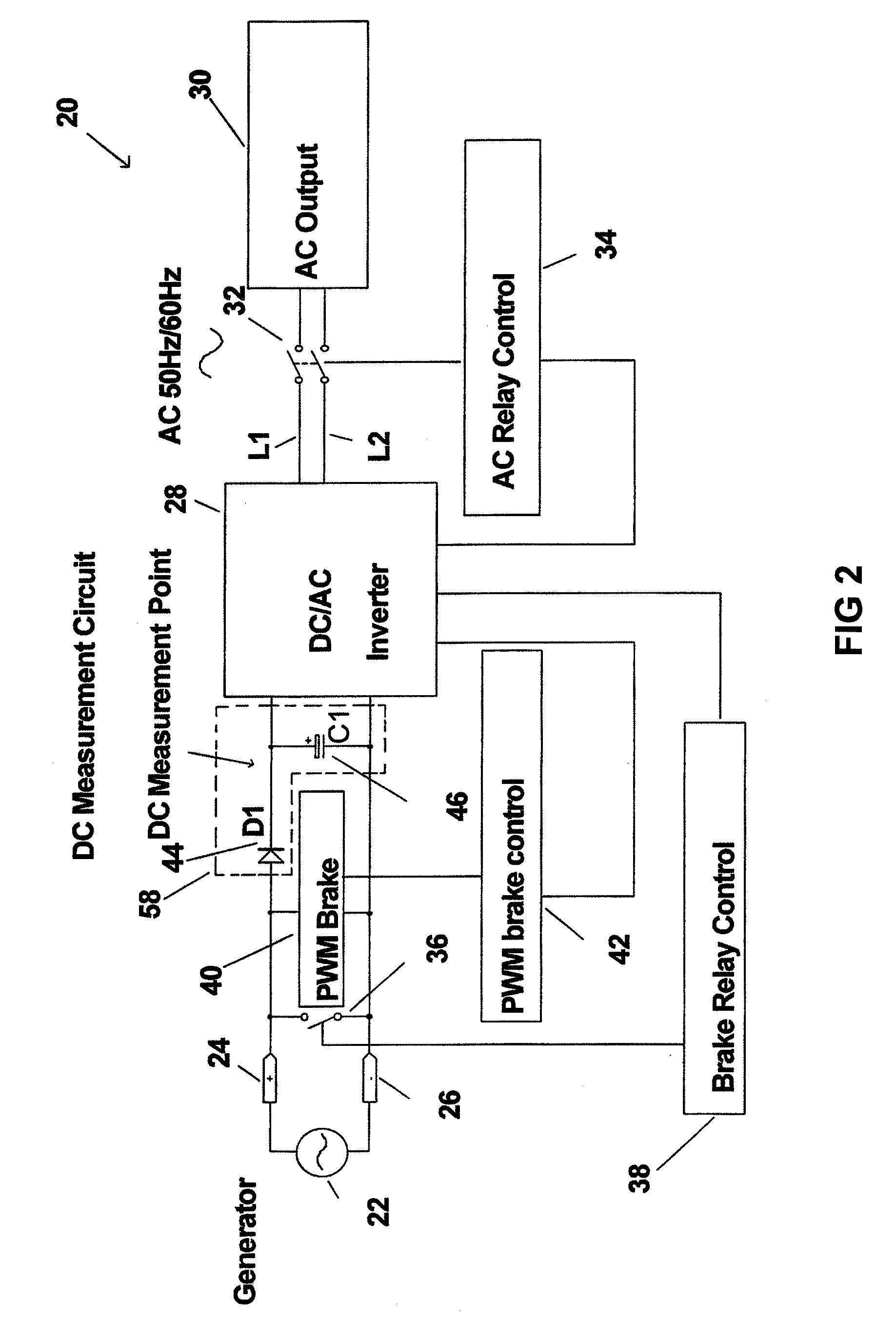
[0032]FIG. 1 is a block diagram of a wind turbine generator system 20 that incorporates a prior art Brake Relay 36 for electronically braking the generator. 22. FIG. 2 is a block diagram of a wind turbine generator system 20 that incorporates a prior art Brake Relay 36 for electronically braking the generator 22 and additionally incorporates a PWM Brake 40 that is coordinated with the prior art Brake Relay 36. FIGS. 3-5 relate to a PWM Brake Control Circuit 42 minus the novel speed sensing circuit in accordance with the present invention. FIGS. 6-8 relate to the novel speed sensing circuit in accordance with the present invention.

[0033]As mentioned above, some known systems utilize a brake relay, used to short out the wind turbine generator output for a nominal period, such as 10 seconds or more, any time the generator voltage exceeds a threshold level indicative of an over speed condition (i.e “first threshold voltage”). Thus, during conditions when high wind speeds exist and the o...


PUM


Abstract

A protection circuit for a wind turbine generator that includes a PWM Brake that works in conjunction with known Brake Relays is disclosed. The Brake Relay is used to short the generator output terminals at a first threshold voltage. The PWM Brake includes one or more switching devices, coupled across the generator output. The PWM Brake is under the control of a PWM Brake Control Circuit which actuates the PWM Brake at a second threshold voltage that is relatively lower than the first threshold voltage. In accordance with an important aspect of the invention, the PWM Brake Control Circuit includes a novel speed sensing circuit for providing a signal representative of the speed of the turbine generator The novel speed sensing circuit eliminates the need to mount a speed sensor on the pole top mounted turbine generator. As such, the need for adding cabling from the pole top mounted wind turbine generator is eliminated. The novel speed sensing circuit provides a signal representative of the rotational speed of the turbine generator based upon the duty cycle of a pulse width modulated (PWM) signal that is derived from the drive signal developed by the PWM Control Circuit. This signal is used to alternatively actuate and close the Brake Relay to minimize actuation of the centrifugal switch.

Description

CROSS REFERENCE TO RELATED APPLICATIONS[0001]This application is a continuation-in-part of U.S. patent application Ser. No. 11 / 377,251, filed on Mar. 16, 2006 now U.S. Pat. No. 7,508,089, hereby incorporated by reference.BACKGROUND OF THE INVENTION[0002]1. Field of the Invention[0003]The present invention relates to a protection circuit for a wind turbine generator and more particularly to a PWM Brake Control Circuit with novel speed sensing.[0004]2. Description of the Prior Art[0005]Wind turbine generator systems are generally known in the art. Examples of such systems are disclosed in U.S. Pat. Nos. 4,565,929; 5,506,453; 5,907,192; 6,265,785; and 6,541,877. Such wind turbine generator systems are also described in U.S. Patent Application Publication Nos. US2002 / 0117861; 2005 / 0034937; 2005 / 0230979; 2005 / 0236839; 2006 / 0006658; and 2006 / 0012182. Such wind turbine generator systems are known to include pole mounted turbine generators. The wind turbine generator systems also include an...

Claims


Application Information

Patent Timeline
Patent Type & Authority Patents(United States)
IPC IPC(8): F03D9/00H02P9/04H02P9/00
CPCF03D7/0244F03D7/0272H02P9/006H02P9/06H02P9/305F05B2270/1011F05B2270/304H02P2101/15Y02E10/723F05B2270/327Y02E10/72
Inventor GUANG, HUANG TAILIU, JIAN FEIHUA, LI WENGAZA, BRIANWENTINK, ROBERT
Owner INT COMPONENTS
Learn More