Fast switch for controlling a differential-pair amplifier

a technology of differential-pair amplifiers and switches, which is applied in the direction of differential amplifiers, amplifiers with semiconductor devices/discharge tubes, dc-amplifiers with dc-coupled stages, etc., can solve the problems of slow particular scheme and conventional process for enabling and disabling amplifiers, and achieve the effect of fast enabling and disabling of differential-pair amplifiers

Active Publication Date: 2010-10-19
MEDIATEK INC
View PDF4 Cites 0 Cited by
  • Summary
  • Abstract
  • Description
  • Claims
  • Application Information

AI Technical Summary

Benefits of technology

[0006]A system and method in accordance with the present invention allows fast enabling and disabling of a differential-pair amplifier. This fast switching technique can be used in the signal paths where the switching time is critical.

Problems solved by technology

This particular scheme is too slow because it requires charging and discharging transistors in the tail current source.
Accordingly, the conventional process for enabling and disabling the amplifier can be too slow for certain applications particularly if the tail current is implemented using bipolar devices.

Method used


Image

  • Fast switch for controlling a differential-pair amplifier
  • Fast switch for controlling a differential-pair amplifier

Examples


Embodiment Construction

[0009]The present invention relates generally to an integrated circuit and more specifically to enabling and disabling a differential-pair amplifier in such a circuit. The following description is presented to enable one of ordinary skill in the art to make and use the invention and is provided in the context of a patent application and its requirements. Various modifications to the preferred embodiment and the generic principles and features described herein will be readily apparent to those skilled in the art. Thus, the present invention is not intended to be limited to the embodiment shown but is to be accorded the widest scope consistent with the principles and features described herein.

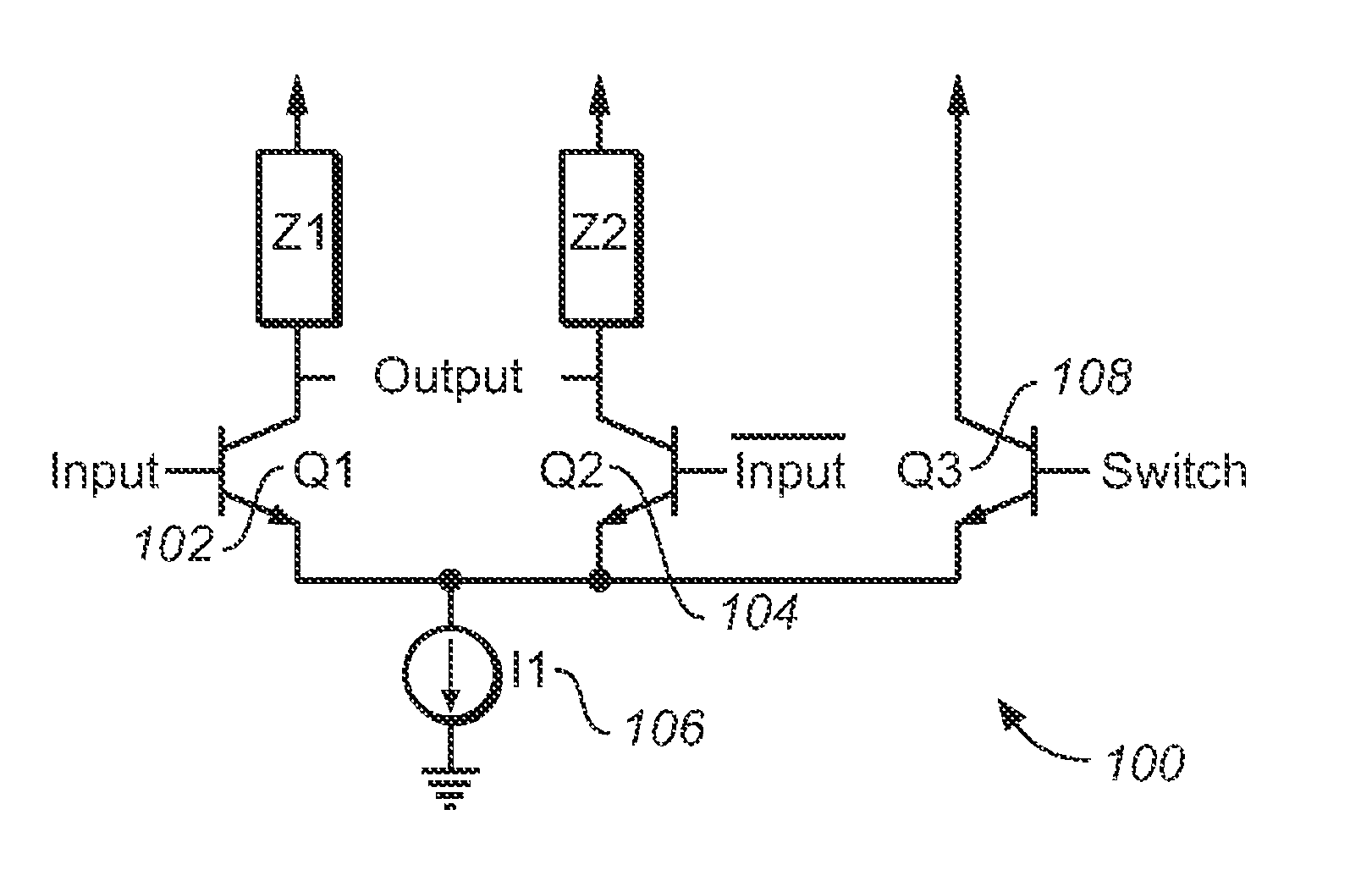
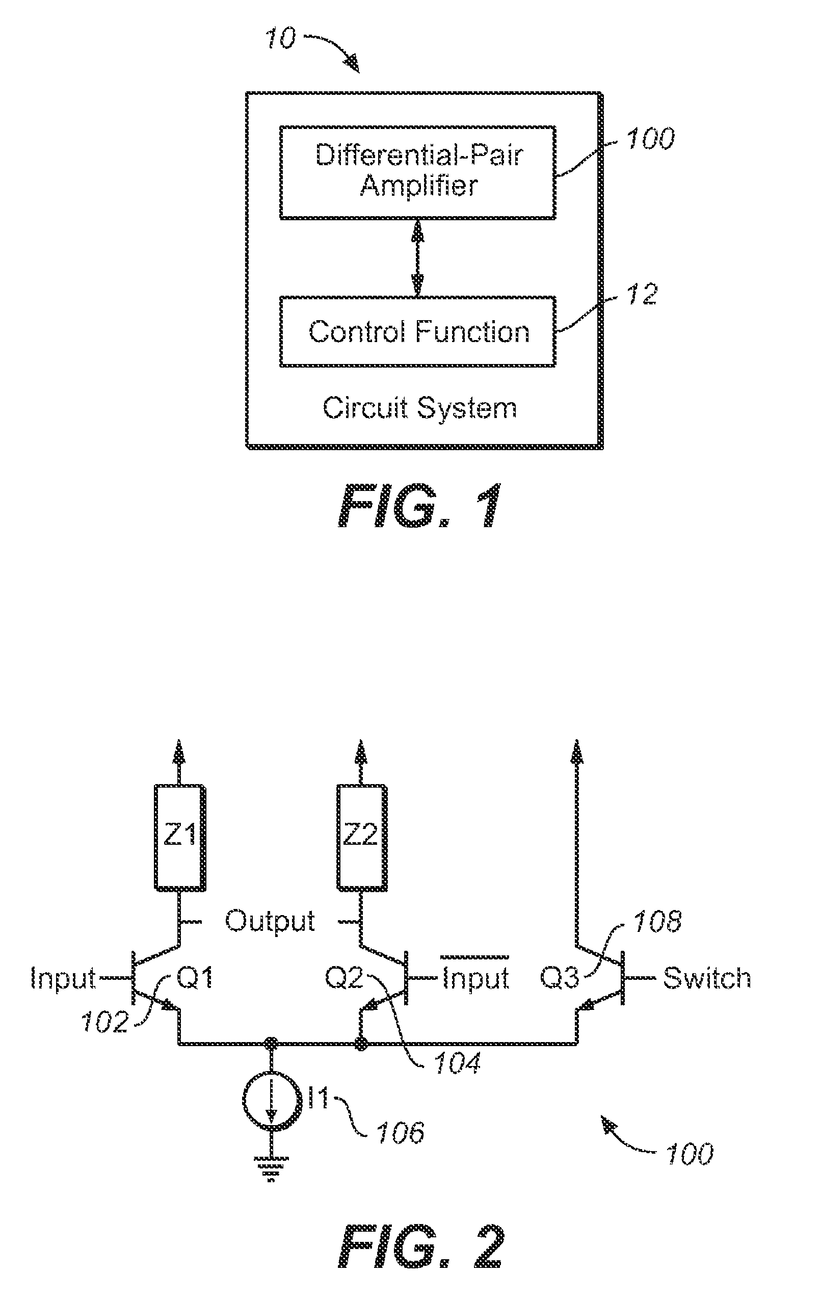
[0010]FIG. 1 is circuit system 10 which utilizes a differential-pair amplifier circuit 100 coupled to a control function 12 within the circuit system to provide a high speed switching function within the circuit system. FIG. 2 shows a differential-pair amplifier circuit 100 according to the prese...


PUM


Abstract

A differential-pair amplifier comprising a transistor pair. The differential-pair amplifier includes a current source coupled to the transistor pair for providing a bias current to the transistor pair. The differential-pair amplifier also includes a switching mechanism coupled to the transistor pair for steering the bias current away from the transistor pair when disabling the amplifier operation. A system and method in accordance with the present invention allows fast enabling and disabling of a differential-pair amplifier. This fast switching technique can be used in the signal paths where the switching time is critical.

Description

FIELD OF THE INVENTION[0001]The present invention relates generally to an integrated circuit and more specifically to enabling and disabling a differential-pair amplifier in such a circuit.BACKGROUND OF THE INVENTION[0002]Differential-pair amplifier is utilized in a variety of applications. Conventionally, the differential-pair amplifier is enabled and disabled by turning on and off a tail current source. The tail current source is utilized to provide bias current to the differential-pair amplifier. Typically, the differential-pair amplifier is enabled and disabled by turning on and turning off the tail current source. This particular scheme is too slow because it requires charging and discharging transistors in the tail current source.[0003]Accordingly, the conventional process for enabling and disabling the amplifier can be too slow for certain applications particularly if the tail current is implemented using bipolar devices.[0004]Accordingly, what is desired is a method which al...

Claims


Application Information

Patent Timeline
Patent Type & Authority Patents(United States)
IPC IPC(8): H03F1/14
CPCH03F3/45085H03F3/72H03F2203/45506H03F2203/7203
Inventor FONG, KENG LEONG
Owner MEDIATEK INC
Why Eureka
Try Eureka