High voltage power supply

a high-voltage power supply and high-voltage technology, applied in emergency protective arrangements for limiting excess voltage/current, instruments, electrographic processes, etc., can solve problems such as abnormal errors, switch opening cover defects, user exposure to high-voltage terminals,

Inactive Publication Date: 2011-06-14
HEWLETT PACKARD DEV CO LP
View PDF2 Cites 0 Cited by
  • Summary
  • Abstract
  • Description
  • Claims
  • Application Information

AI Technical Summary

Benefits of technology

Aspects of the present invention provide a high voltage power supply that detects a change in the load of a device that uses an output power, and when an erroneous load is detected, quickly disables an output, informs a controller of the information, and prevents an input signal of the high voltage power supply.

Problems solved by technology

When a user opens a cover of the image forming device to take out the developer, the user is likely to be exposed to a high voltage terminal.
However, when the cover is open, although an input voltage (24 V) of the high voltage circuit is switched off, the switch for opening the cover may be defective, or other abnormal errors may occur.
In this case, the high voltage terminal is exposed to the user when the developer is taken out of the image forming device, which can cause an electric shock.
As a result, the user may received an electric shock, and the developer of a high voltage output end may be grounded and shorted, which causes circuit damage.

Method used


Image

  • High voltage power supply
  • High voltage power supply
  • High voltage power supply

Examples


Embodiment Construction

Reference will now be made in detail to the present embodiments of the present invention, examples of which are illustrated in the accompanying drawings, wherein like reference numerals refer to the like elements throughout. The embodiments are described below in order to explain the present invention by referring to the figures.

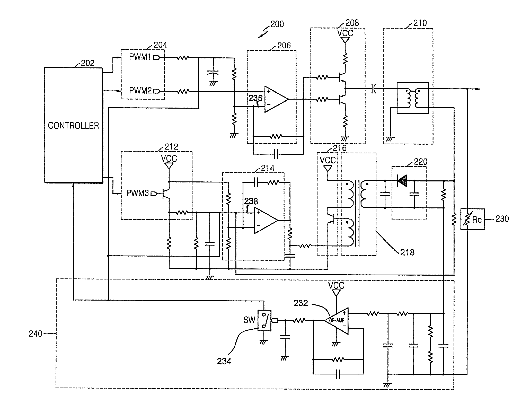
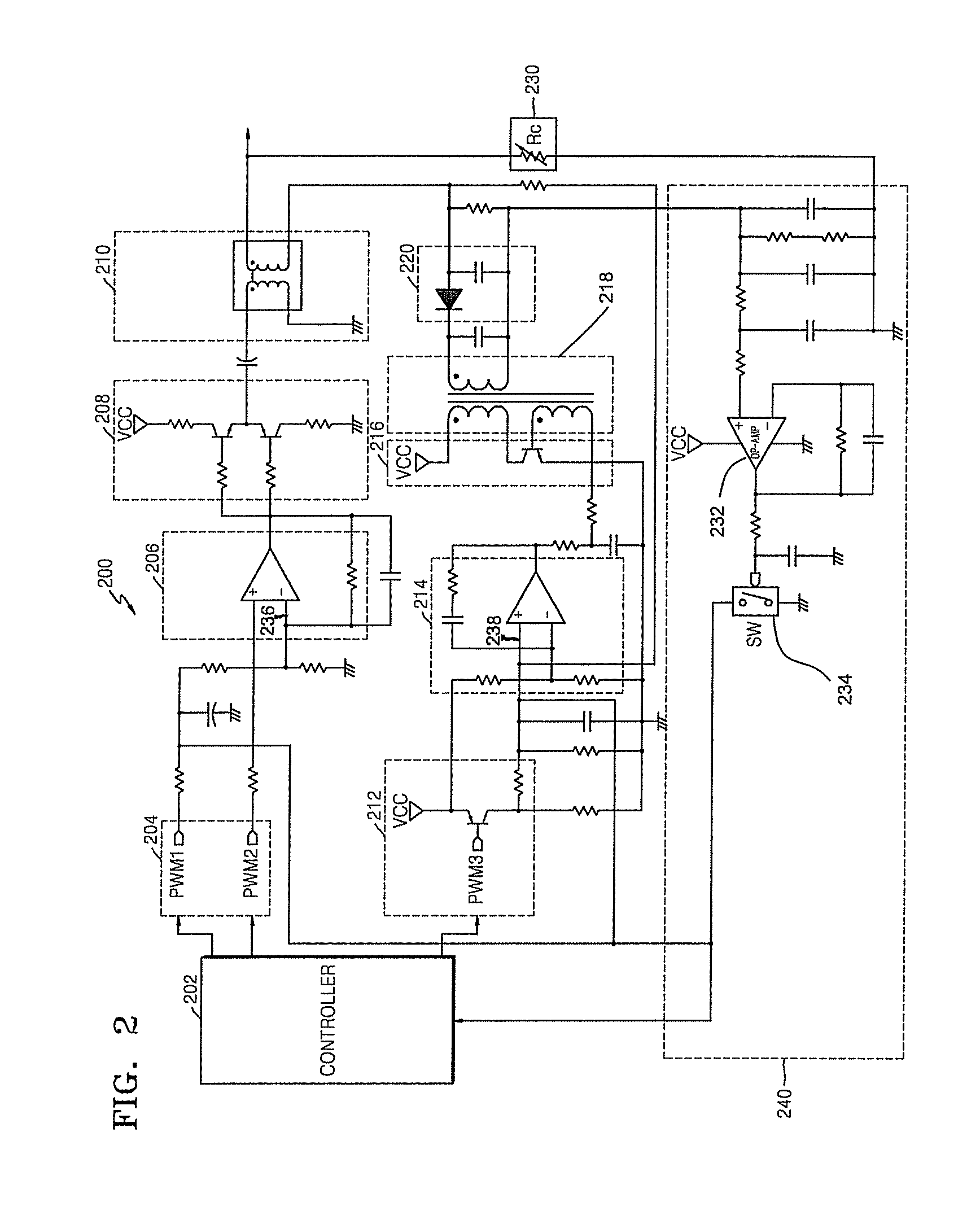
FIG. 2 is a circuit diagram of a high voltage power supply 200 according to an embodiment of the present invention. Referring to FIG. 2, the high voltage power supply200 includes a controller 202 to provide pulse width modulation (PWM) signals PWM1, PWM2, and PWM3. First and second input units 204 and 212 receive the PWM signals PWM1, PWM2, and PWM3 transmitted from the controller 202. First and second comparison units 206 and 214 output comparison signals according to the comparison of the PWM signals PWM1, PWM2, and PWM3 filtered by the first and second input units 204 and 212 and a reference signal. First and second switching units 208 and 216 perform a s...


PUM


Abstract

A high voltage power supply includes a current overflow prevention unit to detect a change in a load of a device that is operated by an output power supplied from a transformer and to ground filtered signals that are input to first and second comparison units according to the detection result.

Description

CROSS-REFERENCE TO RELATED APPLICATIONThis application claims the benefit of Korean Application No-2007-40058, filed on Apr. 24, 2007, in the Korean Intellectual Property Office, the disclosure of which is incorporated herein by reference.BACKGROUND OF THE INVENTION1. Field of the InventionAspects of the present invention relate to a stable high voltage power supply to prevent a current from overflowing therein during contact between a human body and a high voltage unit or during the application of an erroneous load, with regard to a conventional high alternating current (AC) voltage output method used for a non-impact laser printer or multifunctional device.2. Description of the Related ArtFIG. 1 is a circuit diagram of a conventional high voltage power supply 100. Referring to FIG. 1, the conventional high voltage power supply 100 includes a controller 102 to output pulse width modulation (PWM) signals. First and second input units 104 and 112 receive the PWM signals PWM1, PWM2, a...

Claims


Application Information

Patent Timeline
Patent Type & Authority Patents(United States)
IPC IPC(8): H02H7/00
CPCH02H7/125H02H3/12H02M1/44H02M7/003H05K1/0256G03G15/80G03G15/0283
Inventor CHO, JONG-HWA
Owner HEWLETT PACKARD DEV CO LP
Why Eureka
Try Eureka