Enclosure with integrated heat wick

a heat wick and enclosure technology, applied in the field of electric systems, can solve the problems of increasing the risk of electrocution, reducing electrical performance, and heat build-up inside the enclosure without having an efficient effect, and achieve the effect of higher thermal conductivity

Inactive Publication Date: 2010-10-19
SQUARE D CO
View PDF12 Cites 59 Cited by
  • Summary
  • Abstract
  • Description
  • Claims
  • Application Information

AI Technical Summary

Problems solved by technology

The presence of vents can create many problems, such as increasing the risk of electrocution and decreasing electrical performance, e.g., by allowing ingress of liquids, humidity, dust, dirt, corrosives, etc.
One problem associated with ventless enclosures is that heat can build-up inside the enclosure without having an efficient heat path for transfer outside the enclosure.
The heat build-up can have adverse consequences for the electrical equipment located inside the ventless enclosure (e.g., can cause malfunctions, increase risk of fire hazards, etc.).

Method used


Image

  • Enclosure with integrated heat wick
  • Enclosure with integrated heat wick
  • Enclosure with integrated heat wick

Examples


Embodiment Construction

[0014]Although the invention will be described in connection with certain preferred embodiments, it will be understood that the invention is not limited to those particular embodiments. On the contrary, the invention is intended to include all alternatives, modifications and equivalent arrangements as may be included within the spirit and scope of the invention as defined by the appended claims.

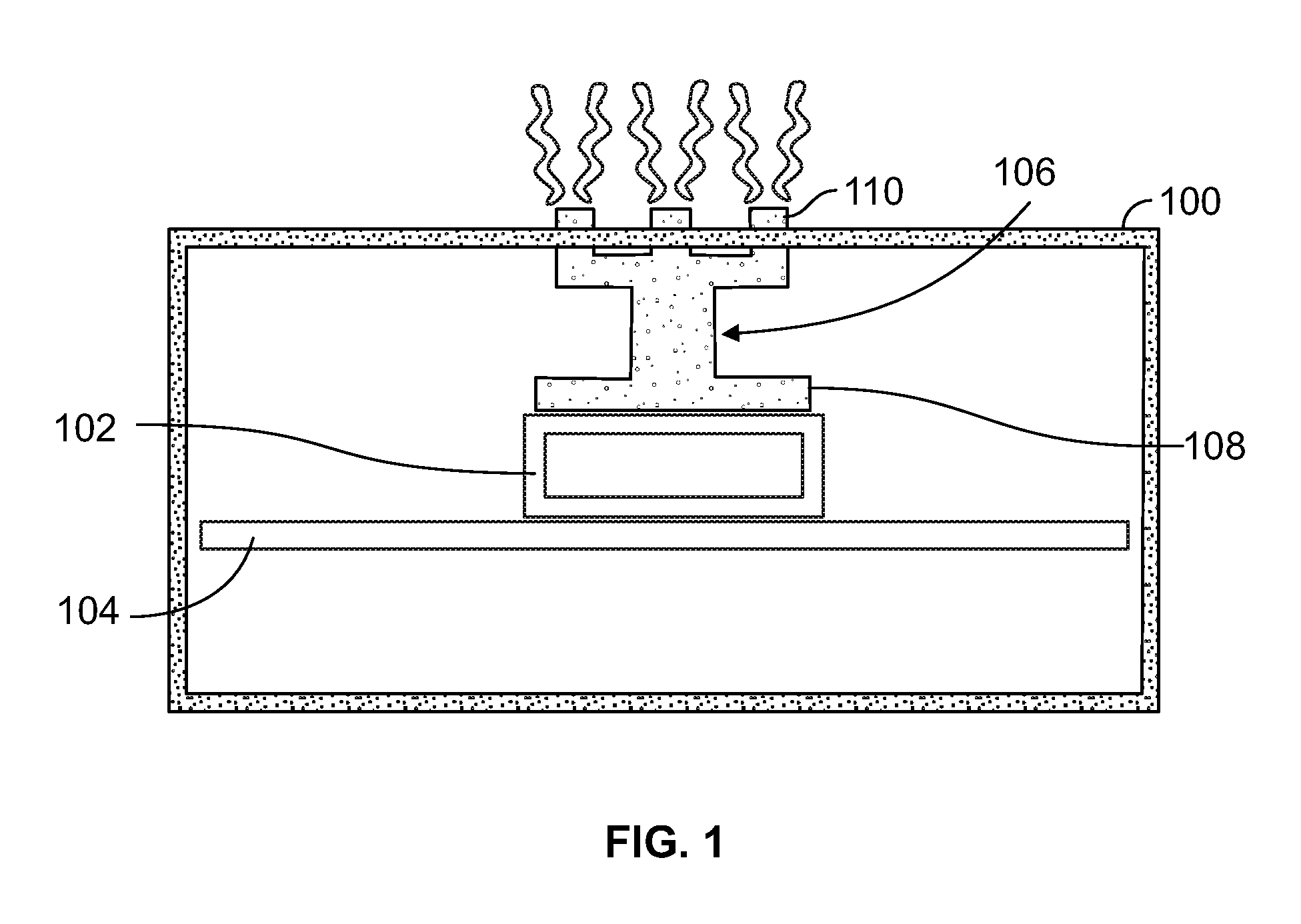
[0015]Referring to FIG. 1, a ventless housing 100 encloses (fully or in part) an electrical heat-generating device 102, which may be optionally located on a supporting structure 104. The ventless housing 100 can efficiently dissipate heat build-up from inside the ventless housing 100 to an exterior environment by using a heat wick 106. The heat wick 106 has an internal member 108, located near the heat-generating device 102, and an external member 110.

[0016]The ventless housing 100 can be used in various electrical applications in which electrical equipment is required, such as a communicatio...


PUM


Abstract

An electrical enclosure system for transferring heat from a closed environment, includes an electrical device having a heat-generating part, and a polymer-based ventless housing for protecting the electrical device from environmental contaminants. The ventless housing fully encloses the electrical device and includes a base layer forming an impact-resistant portion of the ventless housing. The base layer includes one or more open areas in close proximity to the heat-generating part. The ventless housing further includes an integrated thermally conductive layer that forms a heat-flow path for conducting heat away from the heat-generating part towards an exterior environment. The integrated thermally conductive layer is molded around the base layer such that portions of the integrated thermally conductive layer cover the open areas of the base layer.

Description

FIELD OF THE INVENTION[0001]This invention is directed generally to electrical systems, and, more particularly, to a ventless enclosure for dissipating heat from an electrical system.BACKGROUND OF THE INVENTION[0002]Electrical systems in residential, commercial, and industrial applications often include electrical equipment having at least one heat-generating component, e.g., an electrical generator or an electrical transformer. Often, for various reasons, the electrical equipment is located within an electrical enclosure, which serves numerous functions. For example, the electrical enclosure can reduce the likelihood of contact with high-voltage wiring (e.g., reduces risk of electrocution), can improve electrical performance in challenging (e.g., dirty or dusty) environments by reducing contact between contaminants and the electrical equipment, can protect the electrical equipment from physical damage, etc.[0003]To adequately perform its functions, it is generally desired for the e...

Claims


Application Information

Patent Timeline
Patent Type & Authority Patents(United States)
IPC IPC(8): H05K7/20
CPCH05K7/20445H05K7/20409H01F27/025H01F27/22
Inventor GREER, JR., DAVID RANDALLFARAGO, JEFFREY J.
Owner SQUARE D CO
Why Eureka
Try Eureka