Multi-plenum showerhead with temperature control

Inactive Publication Date: 2014-08-21
NOVELLUS SYSTEMS
View PDF10 Cites 75 Cited by
  • Summary
  • Abstract
  • Description
  • Claims
  • Application Information

AI Technical Summary

Benefits of technology

[0024]In some implementations, a method for using a showerhead for semiconductor processing operations is provided. The showerhead may include a precursor delivery plate with a first side and an opposing second side and a radical diffuser plate with a first side and an opposing second side. The second side of the radical diffuser plate may face the first side of the precursor delivery plate. The apparatus may also include a thermal isolator interposed between the precursor delivery plate and the radical diffuser plate. The apparatus may also include a pattern of radical through-holes. Each of the radical through-holes may pass through the precursor delivery plate, the radical diffuser plate, and the thermal isolator. Each of the radical through-holes may also have a hole center axis that is substantially normal to the precursor delivery plate, the radical diffuser plate, and the thermal isolator and may maintain a substantially uniform cross-sectional area perpendicular to the hole center axis of the radical through-hole through the precursor delivery plate, the radical diffuser plate, and the thermal isolator. The method may include maintaining the precursor delivery plate at a first temperature; maintaining the radical diffuser plate at a second temperature; providing a first process gas via the gas delivery holes while the precursor delivery plate is at the first temperature; and providing a second process gas via the radical through-holes while the radical diffuser plate is at the second temperature.
[0025]In some implementations, a reactor for semiconductor processing operations may be provided. The reactor may include a reaction chamber, a wafer support located within the reaction chamber, and

Problems solved by technology

Plasma conversion, however, may also be damaging to the wafer, e.g., by oxidizing t

Method used


Image

  • Multi-plenum showerhead with temperature control
  • Multi-plenum showerhead with temperature control
  • Multi-plenum showerhead with temperature control

Examples


Embodiment Construction

[0058]Examples of various implementations are illustrated in the accompanying drawings and described further below. It will be understood that the discussion herein is not intended to limit the claims to the specific implementations described. On the contrary, it is intended to cover alternatives, modifications, and equivalents as may be included within the spirit and scope of the invention as defined by the appended claims. In the following description, numerous implementation-specific details are set forth in order to provide a thorough understanding of the present invention. The present invention may be practiced without some or all of these implementation-specific details. In other instances, well-known process operations have not been described in detail in order not to unnecessarily obscure the present invention.

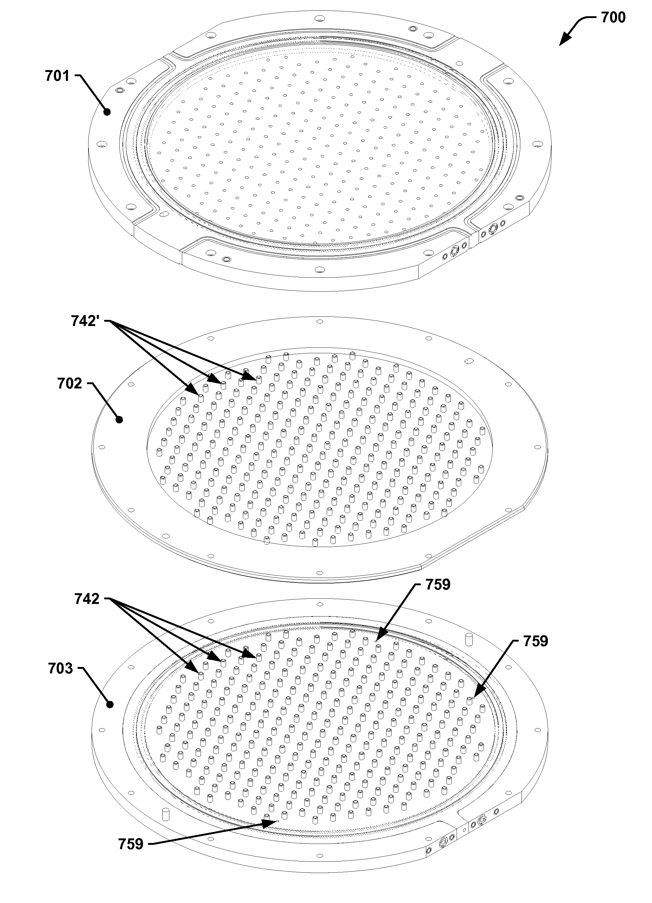
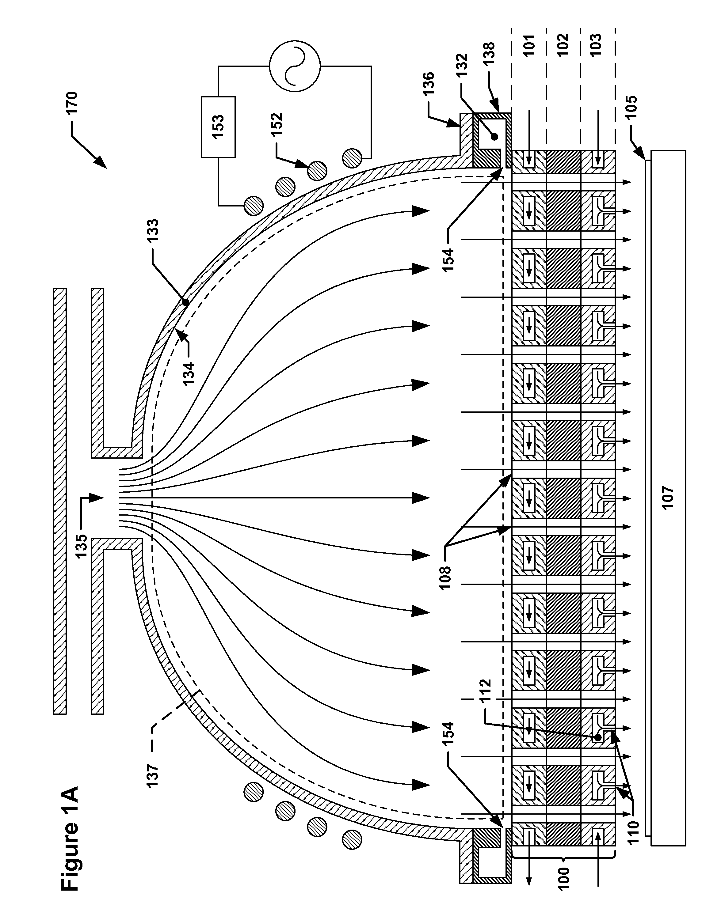
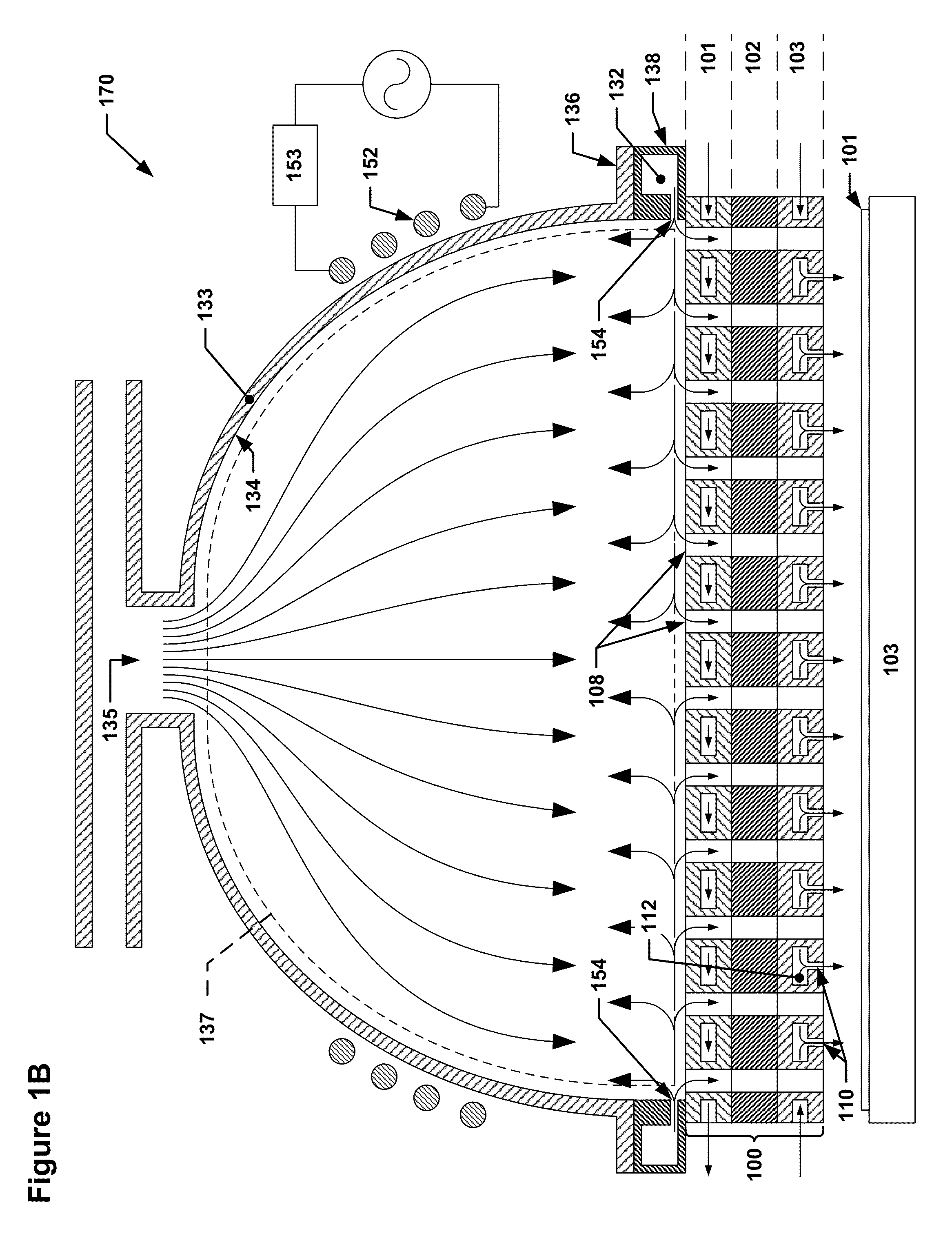
[0059]Described herein are various implementations of a tri-partitioned faceplate assembly for a showerhead for use with remote plasma sources, as well as other featur...


PUM

PropertyMeasurementUnit
Temperatureaaaaaaaaaa
Lengthaaaaaaaaaa
Diameteraaaaaaaaaa

Abstract

An apparatus for use with radical sources for supplying radicals during semiconductor processing operations is provided. The apparatus may include a stack of plates or components that form a faceplate assembly. The faceplate assembly may include a radical diffuser plate, a precursor delivery plate, and a thermal isolator interposed between the radical diffuser plate and the precursor delivery plate. The faceplate assembly may have a pattern of radical through-holes with centerlines substantially perpendicular to the radical diffuser plate. The thermal isolator may be configured to regulate heat flow between the radical diffuser plate and the precursor delivery plate.

Description

CROSS REFERENCE TO RELATED APPLICATIONS[0001]This application claims benefit under 35 U.S.C. §119(e) to U.S. Provisional Application Nos. 61 / 765,432, filed Feb. 15, 2013, and 61 / 770,251, filed Feb. 27, 2013, both titled “MULTI-PLENUM SHOWERHEAD WITH TEMPERATURE CONTROL,” which are both hereby incorporated by reference herein in their entireties.BACKGROUND OF THE INVENTION[0002]Semiconductor processing tools often use radical sources to distribute radicalized process gas across a semiconductor wafer during processing, e.g., during chemical vapor deposition (CVD) or atomic layer deposition (ALD) processing. Such radical sources may include a faceplate that faces the wafer during processing, and a number of gas distribution holes may be distributed across the faceplate to facilitate radicalized gas delivery to the wafer from within the radical source.[0003]During some semiconductor manufacturing processes, e.g., plasma-enhanced chemical vapor deposition (PECVD), semiconductor fabricati...

Claims


Application Information

Patent Timeline
IPC IPC(8): H01L21/02F28F3/02H01L21/67
CPCH01L21/02271H01L21/67017H01L21/02109F28F3/02C23C16/4404C23C16/452C23C16/45565C23C16/45574H01J37/321H01J37/3244H01J37/32522
Inventor BREILING, PATRICK G.VARADARAJAN, BHADRI N.PETRAGLIA, JENNIFER L.VAN SCHRAVENDIJK, BART J.LEESER, KARL F.SRIRAM, MANDYAM AMMANJEEBATZER, RACHEL E.
Owner NOVELLUS SYSTEMS
Why Eureka
Try Eureka