Thick-thin burner

A technology of thick-thin combustion and thick-thin separation, applied in the direction of burner, combustion method, combustion type, etc., can solve the problems of corroded air preheater, shutdown and renovation, ammonia escape, etc., to reduce pipeline wear, expand cross-sectional area, flow even line effect

Active Publication Date: 2020-06-05
SHANGHAI UNIVERSITY OF ELECTRIC POWER
View PDF18 Cites 2 Cited by
  • Summary
  • Abstract
  • Description
  • Claims
  • Application Information

AI Technical Summary

Problems solved by technology

[0003] Current Power Plant Reduces NO x The most common way is the SCR method and the SNCR method, but as the requirements for environmental protection become lower and lower, more and more ammonia is required, which leads to ammonia escape, and the ammonia gas will undergo complex chemical reactions with the components in the flue gas to form hydrogen sulfate Ammonia and ammonia bisulfate will block and corrode the air preheater, greatly affecting the life of the air preheater, and in severe cases, it will lead to shutdown for renovation

Method used


Image

  • Thick-thin burner
  • Thick-thin burner

Examples


Embodiment

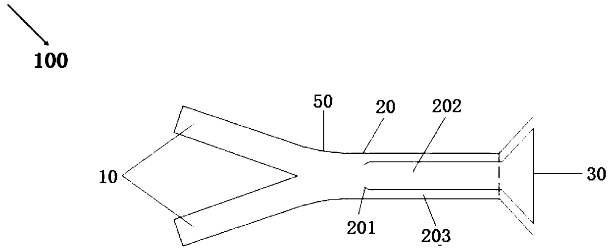
[0016] figure 1 It is a structural schematic diagram of the rich-lean burner in the embodiment of the present invention.

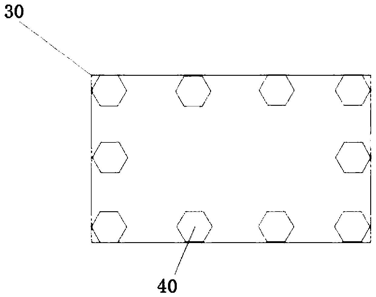
[0017] Such as figure 1 As shown, the rich-lean burner 100 of the present embodiment is connected with the primary air duct to separate the primary air pulverized coal flow for thick-lean separation. The rich-lean burner 100 includes: pulverized coal inlet pipe 10, horizontal main pipe 20, spout 30 and blunt body Member 40.

[0018] One end of the two pulverized coal inlet pipes 10 is a pulverized coal inlet, and the other end intersects each other so that the space between the two pulverized coal inlet pipes is V-shaped.

[0019] The horizontal main pipe 20 is connected to the intersection of two pulverized coal inlet pipes 10, and deflectors 201 are arranged on the upper and lower sides of the interior, and the part between the deflectors 201 on both sides is the main pulverized coal pipe 202, and the pulverized coal pipe is outside. Auxiliary pipelin...


PUM


Abstract

The invention provides a thick-thin burner. The thick-thin burner comprises two pulverized coal inlet pipelines, a horizontal main pipeline, a spray hole and a plurality of blunt body components, wherein ends of the two pulverized coal inlet pipelines are provided with pulverized coal inlets, and the other ends of the two pulverized coal inlet pipelines are crossed with each other to form a V shape; the horizontal main pipeline is connected to a crossed part of the two pulverized coal inlet pipelines, and a guide plate is arranged inside the horizontal main pipeline, a pulverized coal primarypipeline is arranged inside the guide plate, and a pulverized coal auxiliary pipeline is arranged outside the guide plate; the spray hole is horn-shaped, and is connected to the guide plate; the bluntbody components are distributed at the periphery, close to the outlet end, of the spray hole, the horizontal main pipeline and the pulverized coal inlet pipelines are connected in a 150-degree roundchamfer; through the round chamfer, concentration of pulverized coal at the two sides of the horizontal main pipeline is lower than center concentration, so that primary thick-thin separation of pulverized coal is accomplished; one side, close to the pulverized coal inlet pipelines, of the guide plate and a pulverized coal incoming direction define an angle of 120-150 degrees, so that low-concentration pulverized coal at the two sides of the pulverized coal main pipeline is separated out and enters the pulverized coal auxiliary pipeline; and through the spray hole, pulverized coal cannot be quickly diffused to the boundary, so that center concentration of the pulverized coal at the spray hole is high, and peripheral concentration is low, and therefore, thick-thin separation is accomplished.

Description

technical field [0001] The invention relates to a burner, in particular to a rich-lean burner. Background technique [0002] According to statistics from relevant departments, the annual power generation in 2017 was 6,275.8 billion kwh, of which thermal power generation was 4,611.5 billion kwh, and thermal power generation accounted for nearly 73.5% of the total annual power generation. Energy structure, which also means that my country's electricity will be composed of coal-fired power generation for a long time in the future. With the increasing economic and comprehensive national strength of our country, the accompanying environmental problems are becoming more and more serious. After the improvement of people's living standards, people's pursuit of the environment is getting higher and higher. Therefore, the State Council and various localities have put forward stricter requirements for pollutant discharge standards. . In December 2015, the State Council proposed the co...

Claims


Application Information

Patent Timeline
Patent Type & Authority Applications(China)
IPC IPC(8): F23D1/00
CPCF23D1/00F23D2201/10
Inventor 李彦何安武
Owner SHANGHAI UNIVERSITY OF ELECTRIC POWER
Why Eureka
Try Eureka