
Ceramic glow plug equipped with pressure sensor

a glow plug and pressure sensor technology, applied in the direction of lighting and heating apparatus, instruments, machines/engines, etc., can solve the problems of deterioration in the joining strength between the movable member and the holding sleeve, the limited heat transfer path of the movable member, and the deterioration of the joining strength. , to achieve the effect of reducing the influence of heat on the joint part between the holding sleeve and the movable member,

Active Publication Date: 2016-08-23
NGK SPARK PLUG CO LTD
View PDF24 Cites 2 Cited by
  • Summary
  • Abstract
  • Description
  • Claims
  • Application Information

AI Technical Summary

Benefits of technology

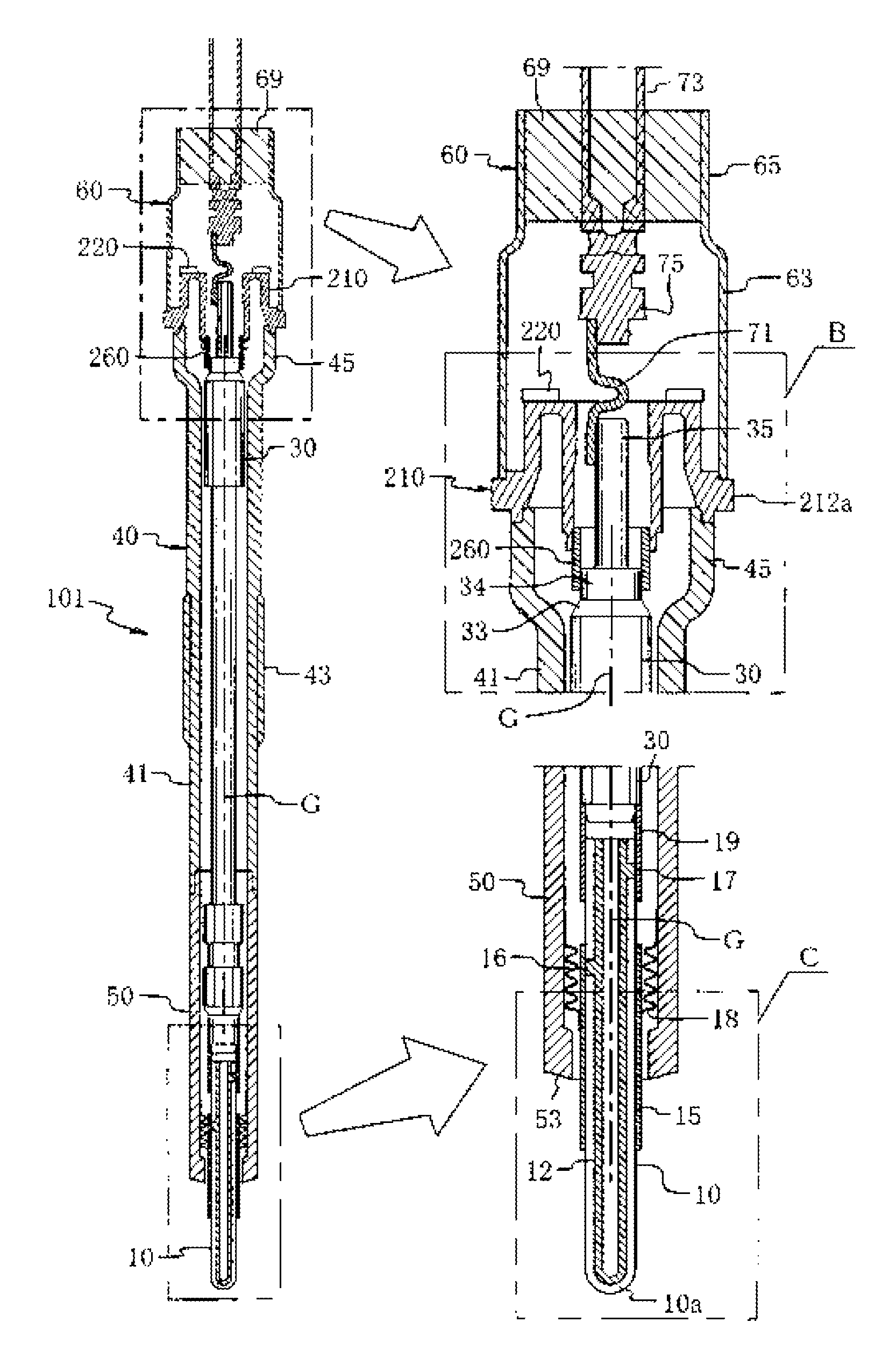
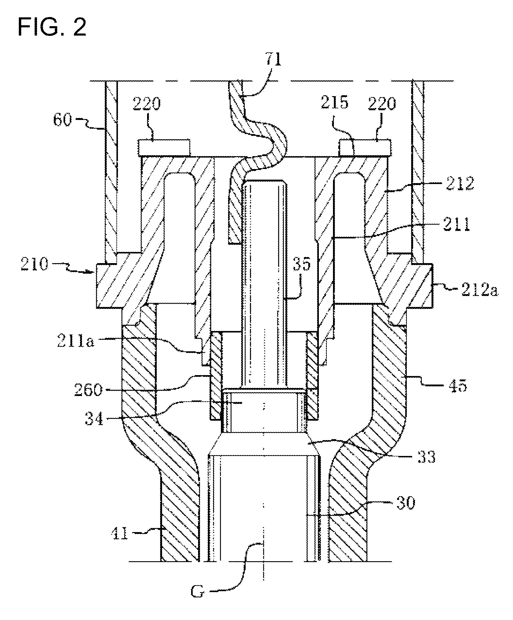
The present invention relates to a ceramic glow plug with a pressure sensor. The technical effects of the invention include reducing heat propagation to the joint part between the holding sleeve and the movable member, restraining deterioration in joining strength, and preventing damage to the ability to function as a pressure sensor resulting from deterioration in airtightness with respect to combustion gas. These effects are achieved by positioning the heat-generating main portion forward of the holding sleeve and the joint part, and by using an electrically insulating ceramic with high thermal conductivity to facilitate heat propagation.

Problems solved by technology

Since the movable member transfers a relatively small quantity of heat, the heat transfer path which extends, via the movable member, to the housing and then to the engine head is extremely limited in heat transfer as compared with the ceramic glow plug as described in Patent Document 1.
As a result, a joint part between the movable member and a portion to which the movable member is attached is susceptible to heat, potentially resulting in a deterioration in joining strength therebetween.

Method used


Image

  • Ceramic glow plug equipped with pressure sensor
  • Ceramic glow plug equipped with pressure sensor
  • Ceramic glow plug equipped with pressure sensor

Examples


examples

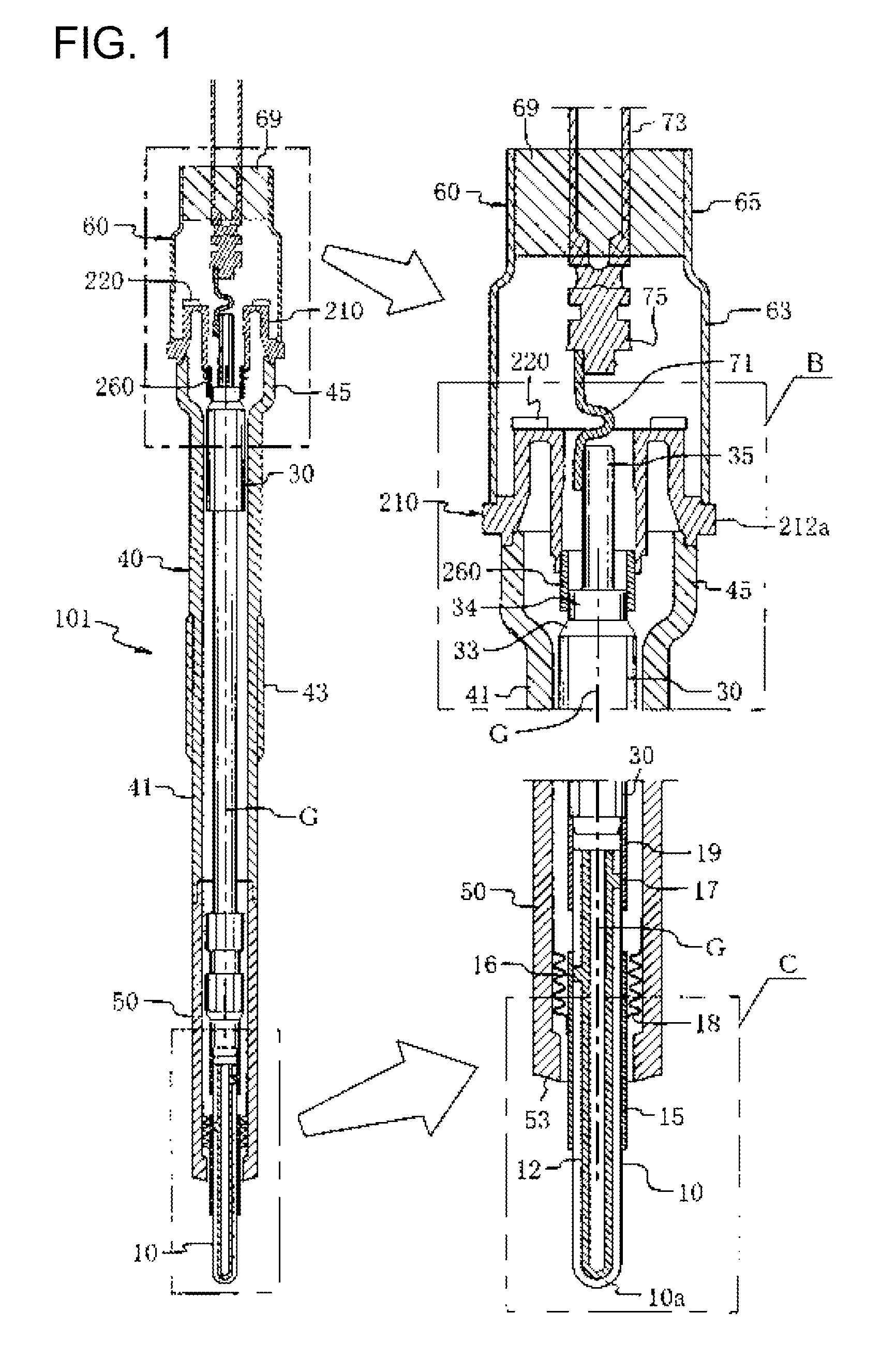
[0084]The temperatures of the joint parts 110 and 110a were measured with respect to the glow plug 101 of an example having the configuration described above in the section of the first embodiment and a glow plug 101a of a comparative example which differed from the glow plug 101 of the first embodiment in the axial length of a heat-generating main portion P1a and the axial length of a heat-generating sub portion P2a as shown in FIG. 7. Similar to FIG. 3, FIG. 7 shows only a ceramic heater 110a, the holding sleeve 15, and the bellows 18.

[0085]As mentioned above, in the glow plug 101 of the example, the axial length of the heat-generating main portion P1 was set to 7.5 mm, and the axial length of the heat-generating sub portion P2 was set to 12.5 mm; furthermore, the axial distance from the forward end of the ceramic heater 10 to the joint part 110 was set to 24 mm. In the glow plug 101a of the comparative example, the axial length of the heat-generating main portion P1a was set to 1...


PUM

PropertyMeasurementUnit
distanceaaaaaaaaaa
surface temperatureaaaaaaaaaa
thicknessaaaaaaaaaa

Abstract

A ceramic glow plug equipped with a pressure sensor including a ceramic heater, a holding device, a housing sleeve, a housing, a movable member and a pressure sensor. A heat-generating main portion P whose resistance is 75% of the total resistance of the ceramic heater is located forward of the forward end of the holding sleeve.

Description

TECHNICAL FIELD[0001]The present invention relates to a ceramic glow plug having a ceramic heater for use in assisting combustion of a diesel engine or performing a like operation, and more particularly to a ceramic glow plug having a built-in pressure sensor capable of measuring a combustion pressure of the engine.BACKGROUND ART[0002]Conventionally, there is known a ceramic glow plug having a ceramic heater (hereinafter, may be referred to as a heater) which uses electrically insulating ceramic as a substrate and in which a resistance heat-generating element formed of a resistor or electrically conductive ceramic is embedded in the substrate or is provided on the outer surface (particularly, on the outer surface of a portion located toward the forward end) of the substrate. Even in use at such a high temperature that, for example, the surface temperature of the forward end of the heater becomes 1,350° C., in contrast to a metal glow plug having a resistance wire coil, the ceramic g...

Claims


Application Information

Patent Timeline
Patent Type & Authority Patents(United States)
IPC IPC(8): F23Q7/00F02P19/02G01M15/08G01L19/00
CPCF02P19/028F23Q7/001G01L19/00G01M15/08F23Q2007/002
Inventor OKINAKA, MANABUYAMAMOTO, YOSHIHIROSUZUKI, HIROYUKISASSA, AKIMITSU
Owner NGK SPARK PLUG CO LTD
Learn More