Closed cabinet for electric device having heat pipe

a technology of electric devices and closed cabinets, which is applied in the direction of electrical equipment, electrical apparatus, electrical apparatus contruction details, etc., can solve the problems of sudden drop in temperature of the surroundings of electric and electronic components installed therein, dew condensation may occur, and the normal operation of the components may be disabled

Inactive Publication Date: 2016-12-01
LSIS CO LTD
View PDF14 Cites 13 Cited by
  • Summary
  • Abstract
  • Description
  • Claims
  • Application Information

AI Technical Summary

Benefits of technology

[0027]According to a closed cabinet for electric devices according to an embodiment of the present disclosure, external air does not circulate through a device accommodation space accommodating electric devices, but is introduced into a separately provided heat dissipation duct to perform the cooling operation. Thereby, the electric device accommodation space may be prevented from being contaminated by rainwater or foreign substances introduced into the space along with the external air.
[0028]In addition, according to an embodiment, the closed cabinet for electric devices employs a heat pipe. Thereby, heat generated from heating elements may be effectively dissipated.

Problems solved by technology

With such convection-type cooling structure, however, when external air is directly introduced into the cabinet 10 at a relatively very low temperature, the temperature of the surroundings of the electric and electronic components installed therein may suddenly drop and thus dew condensation may occur.
As dew condensation occurs, normal operation of the components may be disabled.
However, if a separate dehumidifier is added, the structure of the cabinet may become complex and large.
If a fan including a high capacity is used, power consumption increases.
In addition, if the heat dissipation fan 16 does not operate normally, heat dissipation efficiency of the cabinet for electric devices may be degraded, and accordingly the internal electronic components may be overrated and damaged or the service lives thereof may be shortened.

Method used


Image

  • Closed cabinet for electric device having heat pipe
  • Closed cabinet for electric device having heat pipe
  • Closed cabinet for electric device having heat pipe

Examples


first embodiment

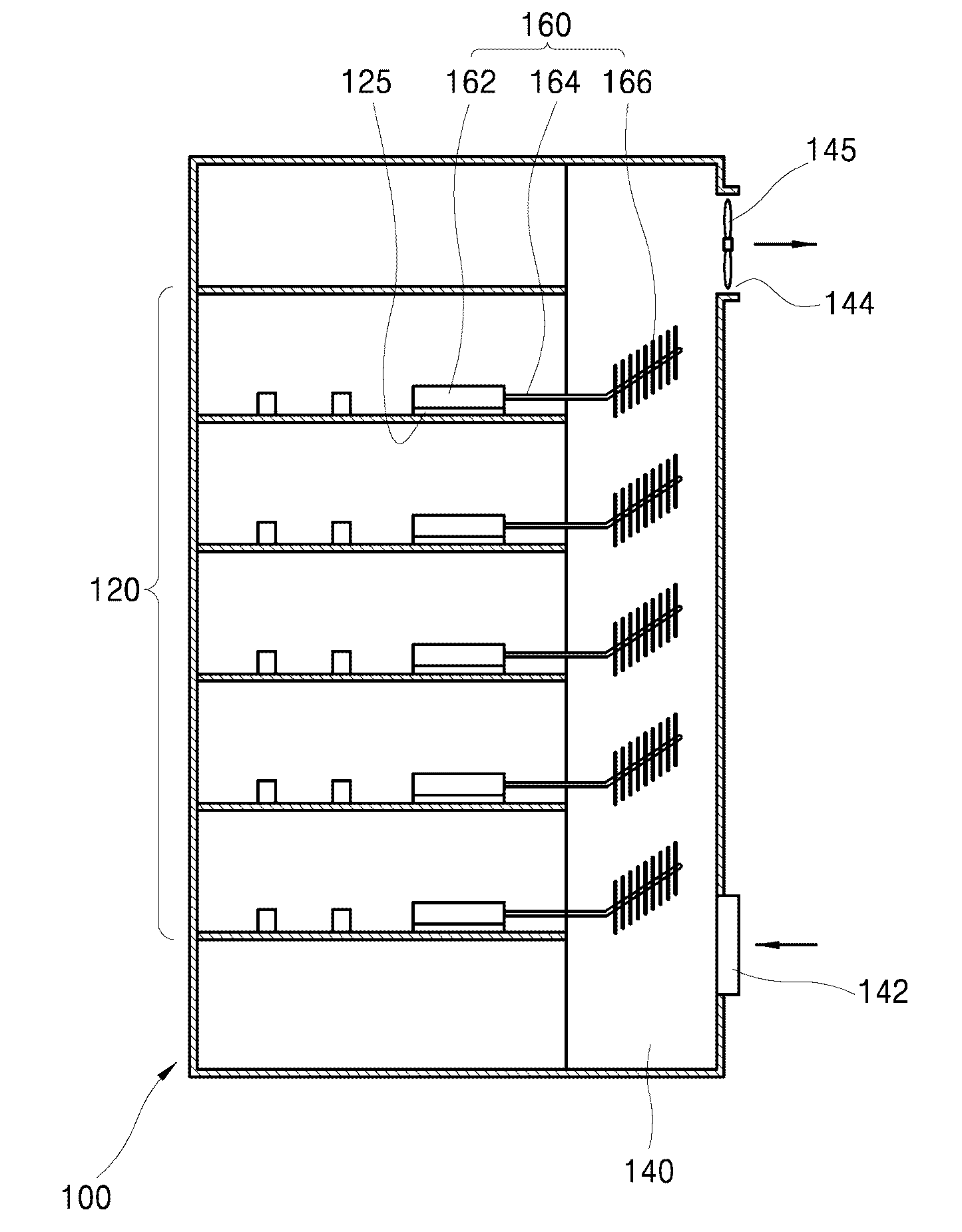
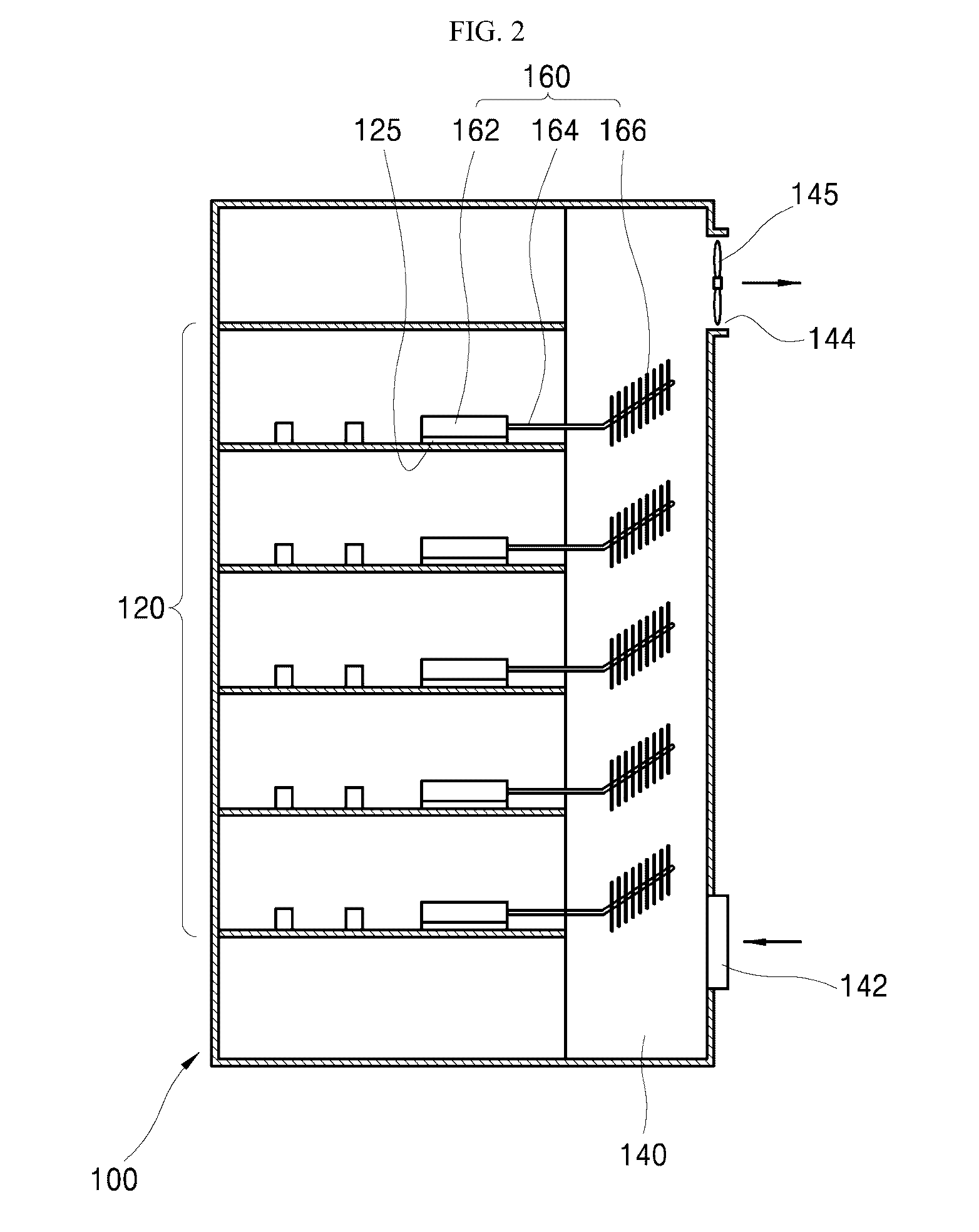
[0050] a section of the heat pipe coupled to the heat dissipation fins 166 is inclined upward.

[0051]The heat pipe 164 is configured to accommodate a heat transfer fluid in a closed body thereof. The heat transfer fluid circulates in the pipe to transfer heat through repetitive evaporation and condensation.

[0052]The evaporation occurs in a part of the pipe buried in the heat sink 162, and the condensation occurs in a part of the pipe to which the heat dissipation fins 166 are attached. Accordingly, as a section of the pipe in which condensation occurs is inclined upward, the condensed heat transfer fluid flows by gravity to a portion (the heat sink) where evaporation occurs. Thereby, the heat transfer fluid circulates and heat is transferred from the heat sink 162 to the heat dissipation fins 166.

[0053]Preferably, the heat dissipation fins 166 are disposed such that the surfaces thereof are arranged in parallel with the vertical direction. Since air is caused to flow upward in the he...

second embodiment

[0055]FIG. 5 is a side view illustrating a heat dissipation means according to the present disclosure.

[0056]For the heat dissipation means according to the second embodiment, the heat dissipation fins 166 are perpendicularly coupled to the heat pipe 164.

[0057]According to the second embodiment, the number of heat dissipation fins 166 installed on the heat pipe 164 per length may be increased.

[0058]For example, if the heat pipe 164 is inclined upward at 30° in the heat dissipation duct, the length of a section of the heat pipe in which the heat dissipation fins 166 are installed is 10 cm, and the spacing between the heat dissipation fins is 2 mm, the vertical installation according to the first embodiment allows 86 heat dissipation fins 166 to be arranged in the heat dissipation duct, while perpendicular installation relative to the heat pipe according to the second embodiment allows 100 heat dissipation fins 166 to be arranged in the heat dissipation duct.

[0059]FIG. 6 is a side view...

third embodiment

[0060] the heat pipe 164 is generally formed in the horizontal direction.

[0061]When a section of the heat pipe 164 where the heat dissipation fins are installed is inclined upward as in the cases of the first and second embodiments, installation of the heat dissipation means 160 may be inconvenient if the internal space of the cabinet for electric devices is limited. In other words, the height of the device accommodation space in the cabinet may not be sufficient to allow the section for installation of heat dissipation fins to be arranged therethrough. In this case, the heat dissipation means 160 needs to be pushed into the device accommodation space from one side of the heat dissipation duct, and installation of the heat dissipation means may not be easy.

[0062]According to the third environment, the heat pipe 164 is generally arranged in a horizontal direction. Thereby, the height of the section thereof for installation of the heat dissipation fins is reduced.

[0063]When the heat p...


PUM


Abstract

In some embodiments, a cabinet for electric device and, more particularly, a closed cabinet for electric devices which has a heat pipe capable of efficiently dissipating heat generated from internal devices, implementing compact design of the cabinet and enhancing durability of the internal devices. In some embodiments, the cabinet includes a device accommodation space providing a closed space to accommodate the electric device, a heat dissipation duct provided separately from the device accommodation space to dissipate heat generated from the device accommodation space, and a heat dissipator including a heat sink attached to a heating element of the device accommodation space; a heat dissipation fin disposed in the heat dissipation duct; a heat pipe configured to transfer heat of the heat sink to the heat dissipation fin.

Description

CROSS REFERENCE TO RELATED APPLICATION[0001]This application claims the benefit of Korean Patent Application No. 10-2015-0072890, filed on May 26, 2015, which is hereby incorporated by reference in its entirety.BACKGROUND[0002]1. Technical Field[0003]The present disclosure relates to a cabinet for electric device and, more particularly, a closed cabinet for electric devices which has a heat pipe capable of efficiently dissipating heat generated from internal devices, implementing compact design of the cabinet and enhancing durability of the internal devices.[0004]2. Description of the Related Art[0005]In general, a cabinet for electric devices includes multiple internal devices (e.g., an inverter) generating heat.[0006]The cabinet is provided with a heat dissipation means to ensure that the internal devices can operate at a proper temperature.[0007]FIG. 1 is a view illustrating a medium / large-size inverter cabinet which is a kind of cabinet for electric devices.[0008]As shown in the...

Claims


Application Information

Patent Timeline
Patent Type & Authority Applications(United States)
IPC IPC(8): H05K7/20
CPCH05K7/20163H05K7/20918H05K7/20145H05K7/20336H05K7/20936
Inventor RYOO, SEONG-RYOUL
Owner LSIS CO LTD
Why Eureka
Try Eureka