
Exhaust gas recirculation cooler

a technology of exhaust gas and cooler, which is applied in the direction of indirect heat exchangers, machines/engines, lighting and heating apparatus, etc., can solve the problems of low ratio of heat to be transferred heat to be transferred from the heat storage material to the egr cooler, and it is difficult to efficiently warm the egr cooler. to achieve the effect of efficiently and effectively generating heat and warm the egr cooler

Active Publication Date: 2019-06-20
TOYOTA JIDOSHA KK
View PDF0 Cites 3 Cited by
  • Summary
  • Abstract
  • Description
  • Claims
  • Application Information

AI Technical Summary

Benefits of technology

The patent aims to provide a solution to efficiently and effectively warm the EGR cooler in vehicles. The technical effect is the development of a technology that allows for better warming of the EGR cooler.

Problems solved by technology

The condensed water generated in this way contains acidic substances such as sulfuric acid (H2SO4), sulfuric anhydride (SO3) or nitric acid (NHO3), and therefore, can cause disadvantages such as the corrosion of components on the EGR gas path.
That is, the ratio of the heat to be transferred to the EGR cooler to the heat transferred from the heat storage material to the EGR cooler is prone to be low.
Therefore, there is a concern that it is difficult to efficiently warm the EGR cooler.
Accordingly, there is a possibility that it is impossible to restrain the generation of the condensed water at the time of the contact between the wall surface of the passage and the EGR gas.
Therefore, there is a concern that it is difficult to effectively warm the EGR cooler when it is necessary to warm the EGR cooler.
Therefore, the ratio of the heat transferred to the wall surface of the gas path to the heat generated by the exothermic body is prone to be high.
Here, if the working gas desorbed from the exothermic body stays in the exothermic body containing portion, when the temperature of the exothermic body decreases to lower than the desorption temperature during, for example, the subsequent stop of the operation of the internal combustion engine, the working gas is adsorbed by the exothermic body again, so that the exothermic body unnecessarily generates heat.
As the length of the exothermic body in the circulation direction of the working gas is longer, it is harder for the working gas to run through the whole of the exothermic body.

Method used


Image

  • Exhaust gas recirculation cooler
  • Exhaust gas recirculation cooler
  • Exhaust gas recirculation cooler

Examples


first embodiment

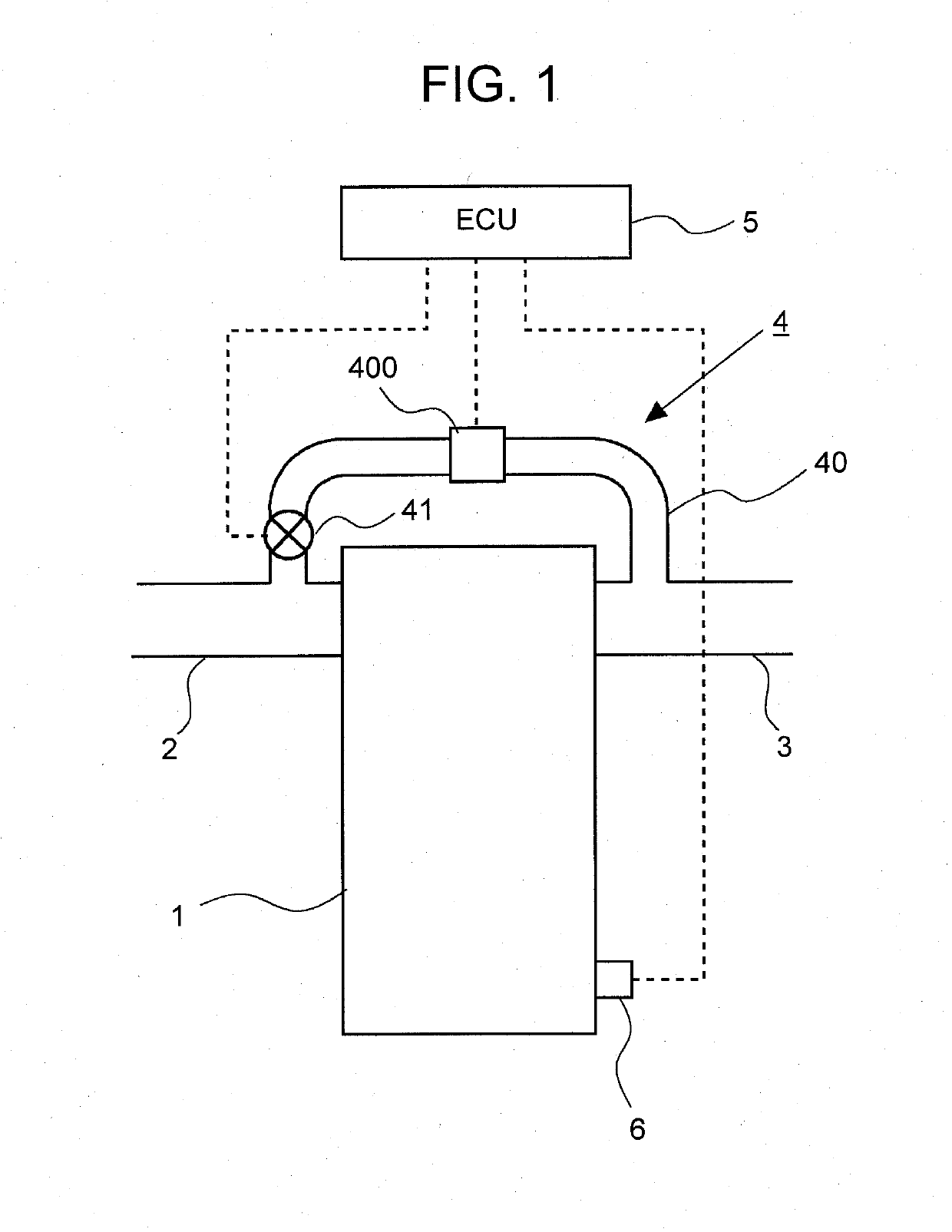
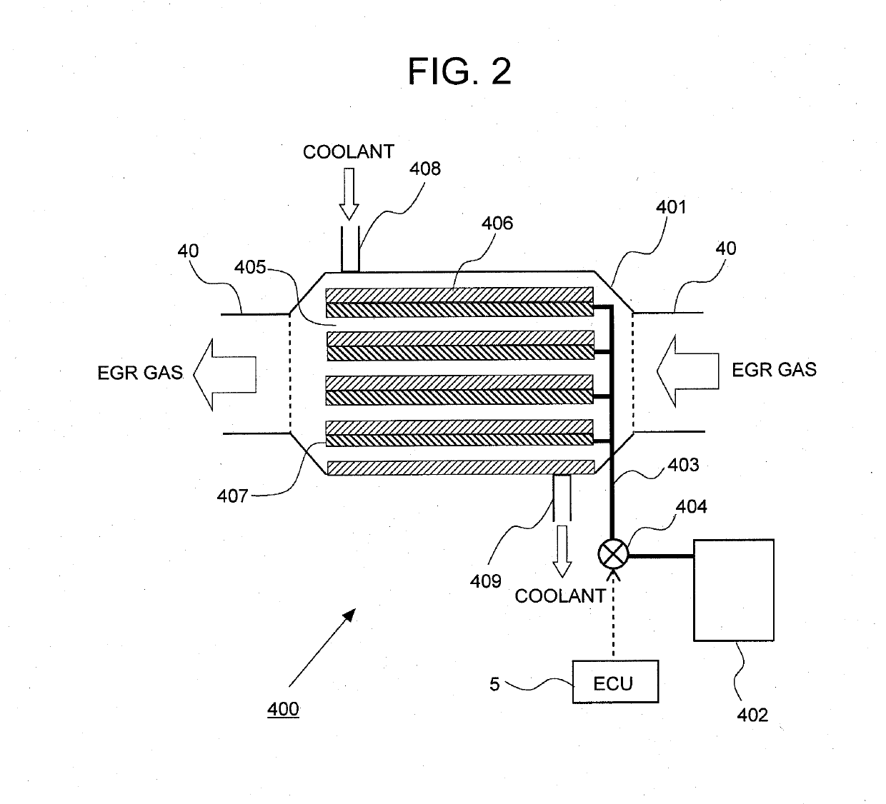
[0043]First, a first embodiment of the disclosure will be described based on FIG. 1 to FIG. 8. FIG. 1 is a diagram showing a schematic configuration of an internal combustion engine to which the EGR cooler of the disclosure is applied. An internal combustion engine 1 shown in FIG. 1 is a spark-ignition internal combustion engine that uses gasoline as fuel or a compression-ignition internal combustion engine that uses diesel fuel as fuel. To the internal combustion engine 1, an intake passage 2 and an exhaust passage 3 are connected. The intake passage 2 is a passage through which fresh air (air) taken from the ambient atmosphere is led into an unillustrated cylinder of the internal combustion engine 1. The exhaust passage 3 is a passage through which gas combusted in the cylinder of the internal combustion engine 1 flows via an unillustrated exhaust gas control catalyst and the like.

[0044]The internal combustion engine 1 is provided with an EGR apparatus 4. The EGR apparatus 4 inclu...

second embodiment

[0087]Next, a second embodiment of the disclosure will be described based on FIG. 9. Here, different configurations from the above-described first embodiment will be described, and the description of the same configurations will be omitted. FIG. 9 is a diagram showing a connection form between the exothermic body containing portion and the communication passage in the embodiment. In FIG. 9, the exothermic body containing portion is shown as a plan view. Further, a white arrow in FIG. 9 shows the flow direction of the EGR gas in the EGR cooler body 401.

[0088]As shown in FIG. 9, the exothermic body (Eh) to be contained in the exothermic body containing portion 407 is formed such that a length L1 in the flow direction of the EGR gas is longer than a length L2 in the direction orthogonal to the flow direction of the EGR gas. The reason is shown as follows. For effectively cooling the EGR gas with the EGR cooler body 401, it is effective that the length (the length of the gas path 405) o...

third embodiment

[0093]Next, a third embodiment of the disclosure will be described based on FIG. 10. Here, different configurations from the first and second embodiments will be described, and the description of the same configurations will be omitted. FIG. 10 is a diagram showing an internal structure of an EGR cooler body in the embodiment.

[0094]As shown in FIG. 10, in an EGR cooler body 401 according to the embodiment, the exothermic body containing portion 407 includes a convergence portion 407a that is disposed at an inlet portion of the EGR cooler body 401 and a plurality of divergence portions 407b that diverges from the convergence portion 407a. The convergence portion 407a is disposed such that the EGR gas flowing into the EGR cooler body 401 comes into contact with the convergence portion 407a before dispersing to a plurality of gas paths 405. Furthermore, the convergence portion 407a is disposed so as to be away from the partition wall forming the gas path 405 and the partition wall form...


PUM


Abstract

An EGR cooler in the disclosure includes: a gas path configured to allow an EGR gas to flow; a refrigerant path configured to perform heat exchange between the EGR gas circulating along the gas path and a refrigerant; an exothermic body containing portion configured such that an exothermic body to generate heat by adsorbing a predetermined working gas is contained within the EGR cooler and at least a part of the exothermic body contacts with a wall surface of the gas path; a working gas tank in which the working gas is stored; and a gas moving apparatus configured to move the working gas stored in the working gas tank, from the working gas tank to the exothermic body containing portion.

Description

INCORPORATION BY REFERENCE[0001]The disclosure of Japanese Patent Application No. 2017-239667 filed on Dec. 14, 2017 including the specification, drawings and abstract is incorporated herein by reference in its entirety.BACKGROUND1. Technical Field[0002]The disclosure relates to an exhaust gas recirculation cooler that performs heat exchange between an exhaust gas recirculation gas and a refrigerant in an internal combustion engine.2. Description of Related Art[0003]In recent years, as an exhaust gas recirculation (EGR) apparatus for recirculating some of exhaust gas discharged from an internal combustion engine, to an intake system, there is known an exhaust gas recirculation apparatus in which an EGR cooler for the heat exchange between an EGR gas and a refrigerant is disposed in the middle of an EGR passage. In the EGR apparatus including the EGR cooler, if the EGR gas flows into the EGR cooler when the atmosphere temperature in the EGR cooler is low, for example, immediately aft...

Claims


Application Information

Patent Timeline
Patent Type & Authority Applications(United States)
IPC IPC(8): F02M26/28F02M26/33F02M26/37F02M26/32
CPCF02M26/28F02M26/33F02M26/37F02M26/32F02M26/25F02M26/30F02M26/05F28F27/00F28D20/003F28D21/0003F02M26/11F02M26/35Y02E60/14F02M2026/001
Inventor SHINAGAWA, TOMOHIROHOTTA, TAKASHIYAMAGUCHI, TAKEOOHASHI, YOSHIOYOSHINAGA, TAIZOMIYOSHI, YUJI
Owner TOYOTA JIDOSHA KK
Learn More