
Light emitted diode circuit

Active Publication Date: 2016-06-16
CHEN FENG CHIEN +2
View PDF8 Cites 2 Cited by
  • Summary
  • Abstract
  • Description
  • Claims
  • Application Information

AI Technical Summary

Benefits of technology

The present invention aims to provide an LED circuit that can effectively reduce power consumption and heat generation.

Problems solved by technology

Generally, a LED circuit has higher temperature in operation which causes a bad effect to whole circuit, therefore, how to utilize a simple circuit architecture to reduce the generated heat when the LED circuit is operating is an important issue.

Method used


Image

  • Light emitted diode circuit
  • Light emitted diode circuit
  • Light emitted diode circuit

Examples


Embodiment Construction

[0013]Certain terms are used throughout the description and following claims to refer to particular components. As one skilled in the art will appreciate, manufacturers may refer to a component by different names. This document does not intend to distinguish between components that differ in name but not function. In the following description and in the claims, the terms “include” and “comprise” are used in an open-ended fashion, and thus should not be interpreted as a close-ended term such as “consist of”. Also, the term “couple” is intended to mean either an indirect or direct electrical connection. Accordingly, if one device is coupled to another device, that connection may be through a direct electrical connection, or through an indirect electrical connection via other devices and connections.

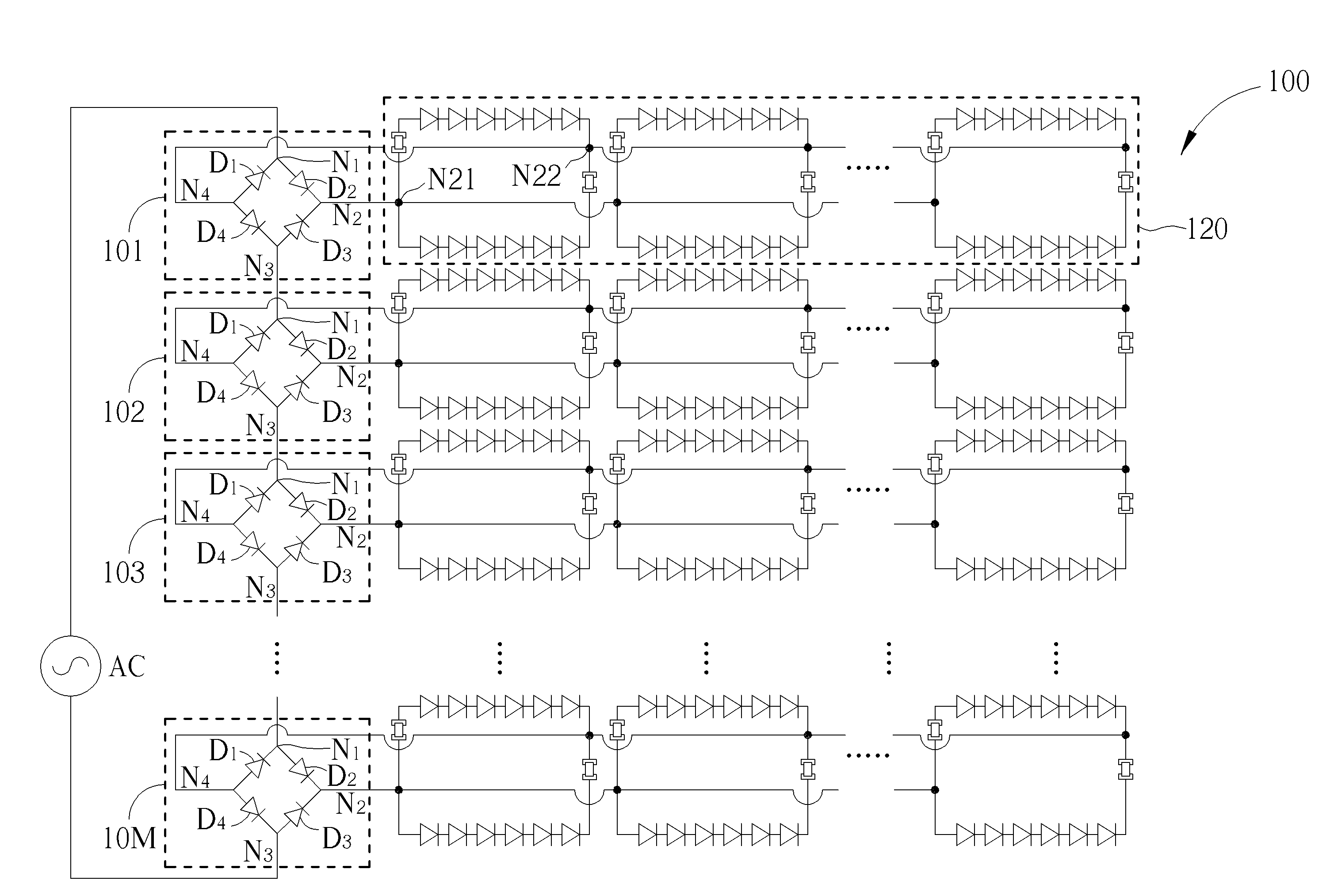
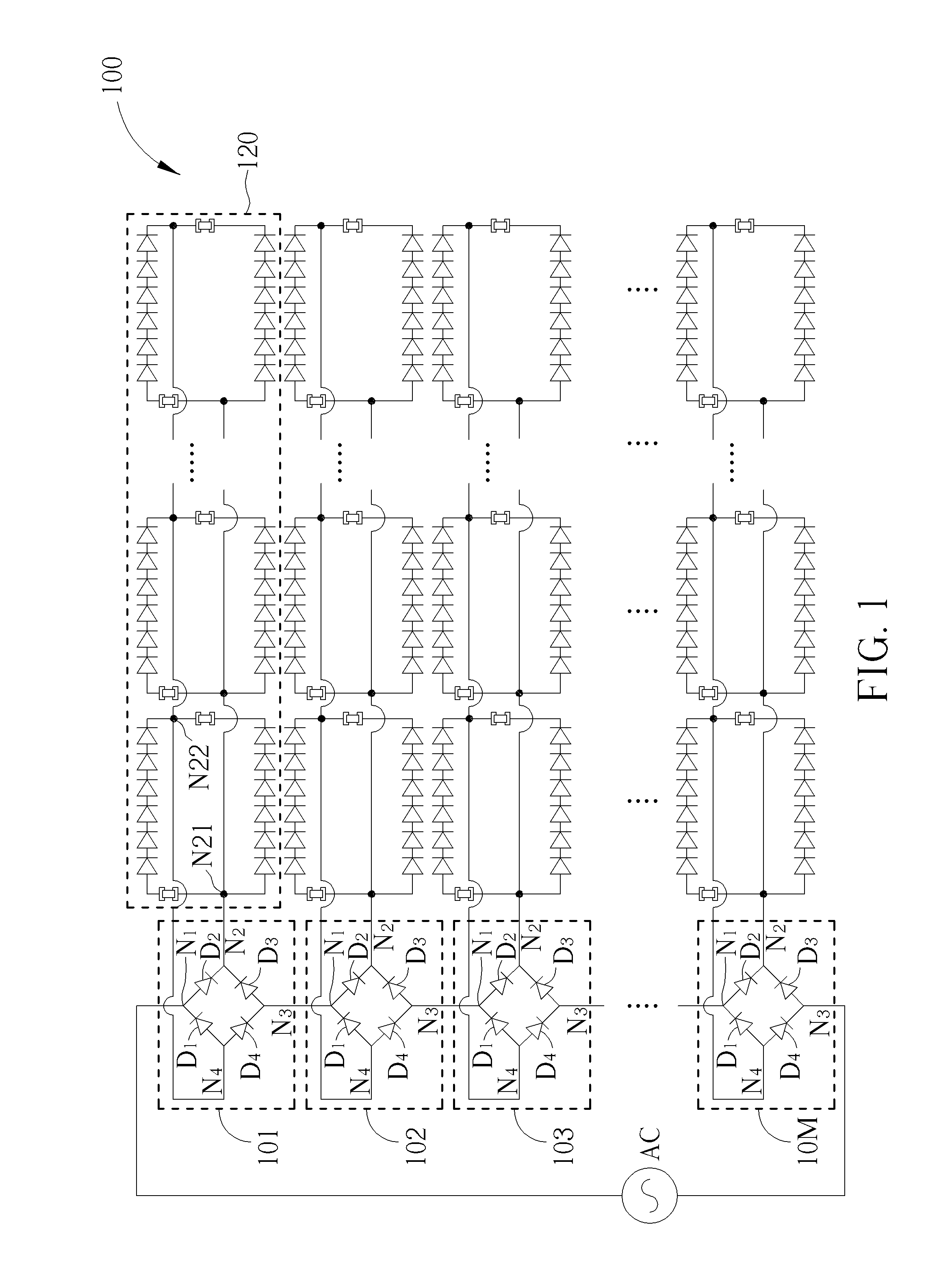
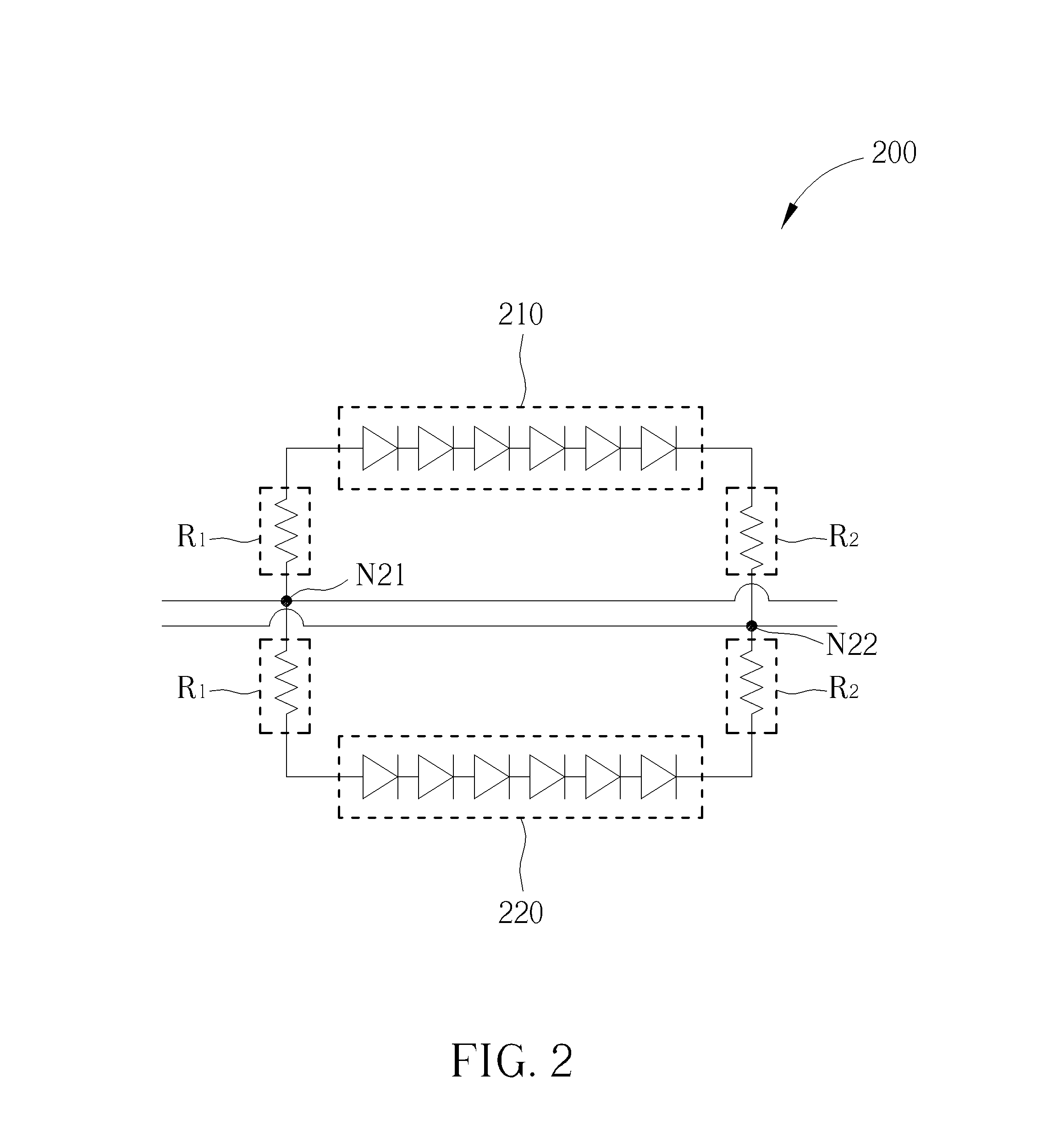
[0014]FIG. 1 is a diagram illustrating an LED circuit 100 according to an embodiment of the present invention. As shown in FIG. 1, the LED circuit 100 comprises a plurality of driving circu...


PUM


Abstract

A light emitted diode circuit includes: a plurality of driving circuits, wherein the plurality of driving circuit are connected in series, and each driving circuit includes a plurality of diodes; and a plurality of loading circuits connected with the driving circuits, respectively; wherein the plurality of driving circuits are arranged for generating a plurality of driving voltages to drive the plurality of loading circuits, respectively.

Description

CROSS REFERENCE TO RELATED APPLICATIONS[0001]This application claims the benefits of U.S. provisional application No. 62 / 090,889 (filed on 2014, Dec., 12). The entire contents of the related applications are incorporated herein by reference.BACKGROUND OF THE INVENTION[0002]1. Field of the Invention[0003]The present invention relates to a diode circuit, and more particularly, to a light emitted diode (LED) circuit that can reduce power consumption effectively and generate less heat.[0004]2. Description of the Prior Art[0005]Generally, a LED circuit has higher temperature in operation which causes a bad effect to whole circuit, therefore, how to utilize a simple circuit architecture to reduce the generated heat when the LED circuit is operating is an important issue.SUMMARY OF THE INVENTION[0006]One of the objectives of the present invention is to provide an LED circuit whose power consumption and the generated heat can be reduced effectively.[0007]According to an embodiment of the pr...

Claims


Application Information

Patent Timeline
IPC IPC(8): H05B33/08H05B44/00
CPCH05B33/0827H05B33/0809H05B45/46
Inventor CHIEN, CHEN-FENG
Owner CHEN FENG CHIEN
Learn More