Catalytic burner for stirling engine

a technology of catalytic burner and stirling engine, which is applied in the direction of catalytic material combustion, combustion types, lighting and heating apparatus, etc. it can solve the problems of enhancing requiring an external heat source to operate, and still exist in the art relating to the enhancement of the efficiency of the operation of the stirling engine. achieve the effect of simple, efficient and effective heat generation

Inactive Publication Date: 2009-05-07
PRECISION COMBUSTION
View PDF14 Cites 20 Cited by
  • Summary
  • Abstract
  • Description
  • Claims
  • Application Information

AI Technical Summary

Benefits of technology

[0017]The present invention provides a simple, efficient and effective method for generating and transferring heat to the heater head of a Stirling Engine. It has now been found that a catalytic reactor comprising catalyst deposited on ultra-short-channel-length metal mesh elements, known as Microlith® and commercially available from Precision Combustion, Inc., located in North Haven, Conn., efficiently and effectively generates heat as a burner within the operative constraints for a Stirling Engine known within the art. More importantly and in contrast to the prior art, the catalytic reactor comprising catalyst deposited on Microlith® ultra-short-channel-length metal mesh elements may be positioned in direct (i.e., non spaced-apart) communication with the heater head thereby providing heat transfer by thermal conduction, the most efficient manner of heat transfer in Stirling Engine applications.

Problems solved by technology

Stirling Engines, however, require an external heat source to operate.
However, a problem still exists in the art with respect to enhancing the efficiency of the operation of a Stirling Engine.
As recognized by one skilled in the art, the uniform burning of a matrix burner element remains a problem.
Unfortunately, the solution offered by Bohn still is too complex and inefficient for desired uses.
Clark teaches that a problem still exists in the art with respect to the effective and efficient transfer of heat to a Stirling Engine heater head as late as 2003.
Another problem with burner devices for a Stirling Engine is described in U.S. Pat. No. 6,513,326 to Maceda, et al.
According to Maceda, heat is not uniformly distributed to the working gas within the heater tubes because a single burner device is used to generate and effectuate the heat transfer.
Unfortunately, the solution offered by Bohn still is too complex and inefficient for desired uses.

Method used


Image

  • Catalytic burner for stirling engine
  • Catalytic burner for stirling engine
  • Catalytic burner for stirling engine

Examples


Embodiment Construction

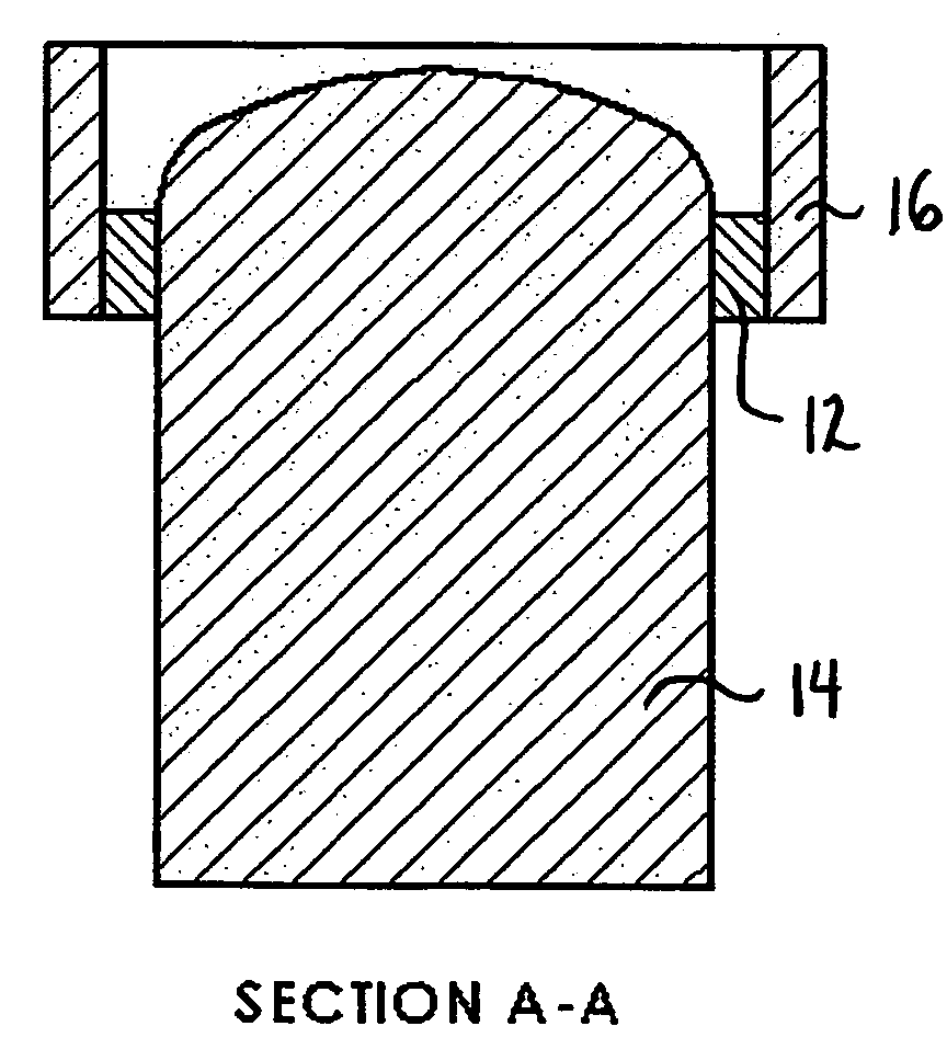
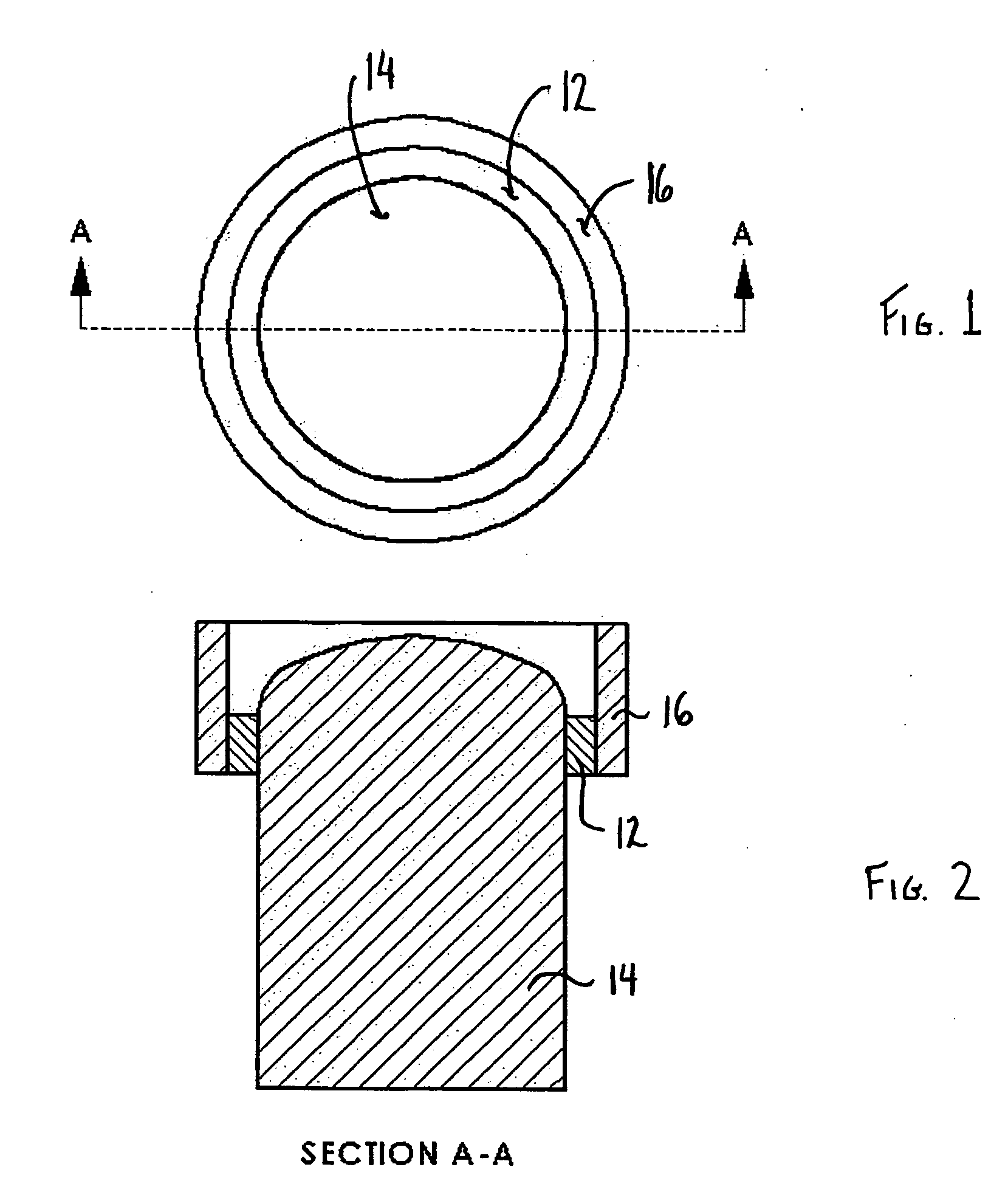
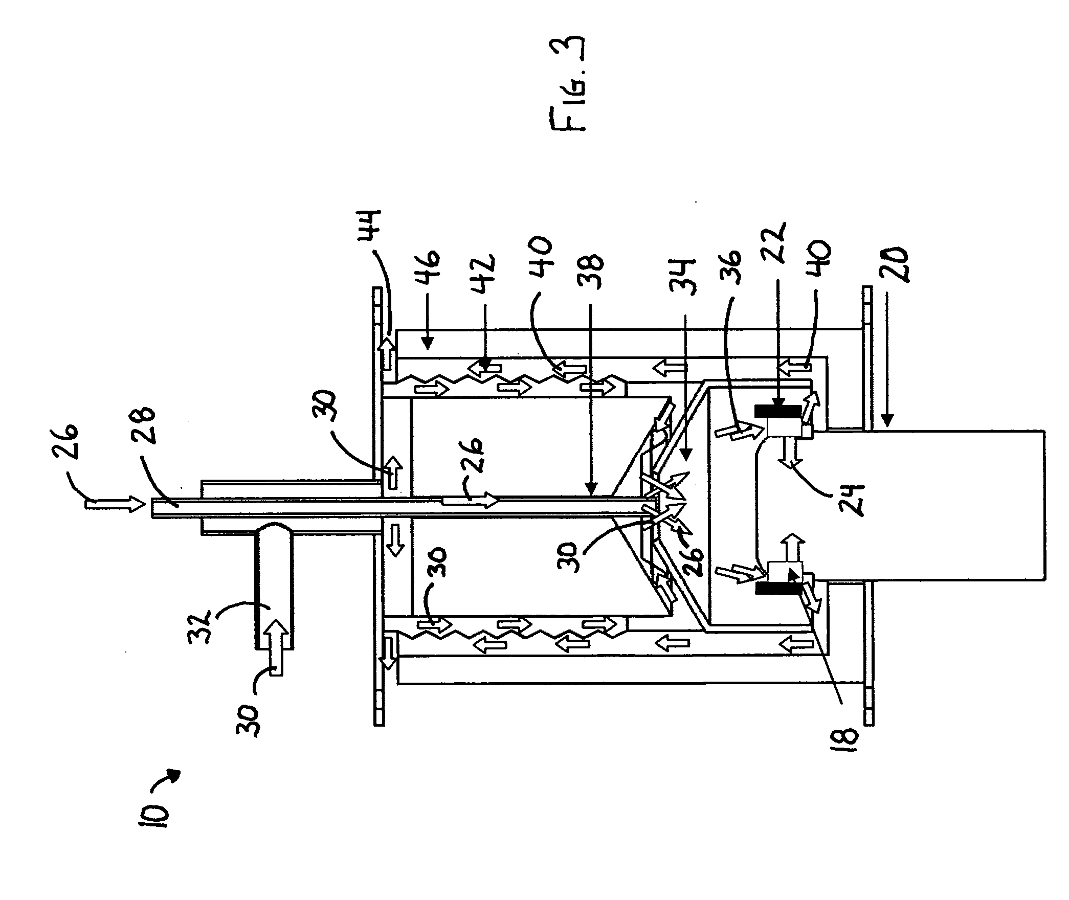
[0026]As shown in FIGS. 1 and 2 and generally referred to as heat conduction method 10 in FIG. 3, catalytic reactor 12 is positioned in communication with heater head 14, and rigidly held in place by catalyst holder 16. Catalytic reactor 12 comprises catalyst deposited on Microlith® ultra-short-channel-length metal mesh elements. The reactor provides heat transfer to heater head 14 by thermal conduction. Catalyst holder 16 also serves as a heat exchanger with respect to the heat generated by the catalytic reactor 12 and transferred to the gases passing over and in proximity to catalyst holder 16.

[0027]As depicted in FIGS. 2 and 3, heat conduction method 10 comprises a catalytic reactor 18 positioned in communication with Stirling Engine heater head 20, and held in place by catalyst holder 22. Catalytic reactor 18 provides heat transfer to heater head 20 by thermal conduction 24 through internal heat acceptor 25. In the embodiment of the invention depicted, fuel 26 is introduced via ...


PUM


Abstract

The invention provides a method for transferring heat by conduction to the internal heat acceptor of an external combustion engine. Fuel and air are introduced and mixed to form an air/fuel mixture. The air/fuel mixture is directed into a catalytic reactor that is positioned substantially adjacent to the heater head. Heat is transferred via conduction from the catalytic reactor to the heater head and the catalytic reaction products are exhausted.

Description

GOVERNMENT RIGHTS[0001]This invention was made with government support under U.S. Contract No. W911-NF-04-1-0238, Subaward No. Y-04-0023. The U.S. government holds certain rights in this invention.FIELD OF THE INVENTION[0002]The present invention is generally directed to a method for providing heat to an external combustion engine. More particularly, the present invention is directed toward providing substantially conductive heat transfer to the internal heat acceptor, commonly referred to the heater head, of a Stirling Engine.BACKGROUND OF THE INVENTION[0003]As is well known in the art, Stirling Engines convert a temperature difference directly into movement. Such movement, in turn, may be converted into mechanical or electrical energy. The Stirling Engine cycle comprises the repeated heating and cooling of a sealed amount of working gas. When the gas in the sealed chamber is heated, the pressure increases and acts on a piston thereby generating a power stroke. When the gas in the ...

Claims


Application Information

Patent Timeline
Patent Type & Authority Applications(United States)
IPC IPC(8): F02G1/043
CPCF02G1/055F02G2254/11F02G2254/70F23C2900/13001F23C13/00F23D11/32F23L15/04Y02E20/34
Inventor ROYCHOUDHURY, SUBIRBERRY, JONATHAN
Owner PRECISION COMBUSTION
Why Eureka
Try Eureka