Catalytic burner apparatus for stirling engine

Active Publication Date: 2008-04-03
PRECISION COMBUSTION
View PDF19 Cites 21 Cited by
  • Summary
  • Abstract
  • Description
  • Claims
  • Application Information

AI Technical Summary

Benefits of technology

[0018] The present invention provides a simple, efficient and effective apparatus for generating and transferring heat to the heater head of a Stirling Engine. It has now been found that a catalytic reactor comprising catalyst deposited on ultra-short-channel-length metal mesh elements, known as Microlith™ and commercially available from Precision Combustion, Inc., located in North Haven, Conn., efficiently and effectively generates heat as a burner wi

Problems solved by technology

Stirling Engines, however, require an external heat source to operate.
However, a problem still exists in the art with respect to enhancing the efficiency of the operation of a Stirling Engine.
As recognized by one skilled in the art, the uniform burning of a matrix burner element remains a problem.
Unfortunately, the solution offered by Bohn still is too complex and inefficient for desired uses.
Clark teaches that a problem still exists in the art with respect to the effectiv

Method used


Image

  • Catalytic burner apparatus for stirling engine
  • Catalytic burner apparatus for stirling engine
  • Catalytic burner apparatus for stirling engine

Examples


Embodiment Construction

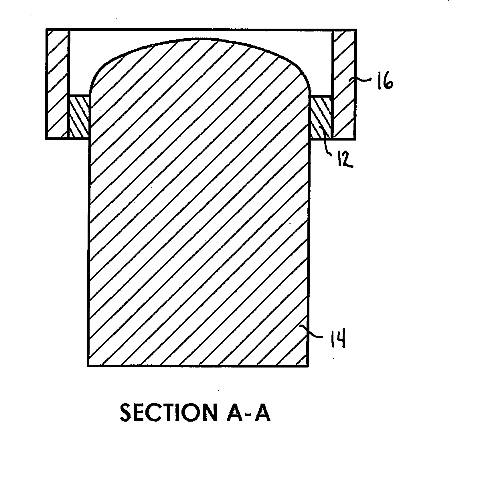
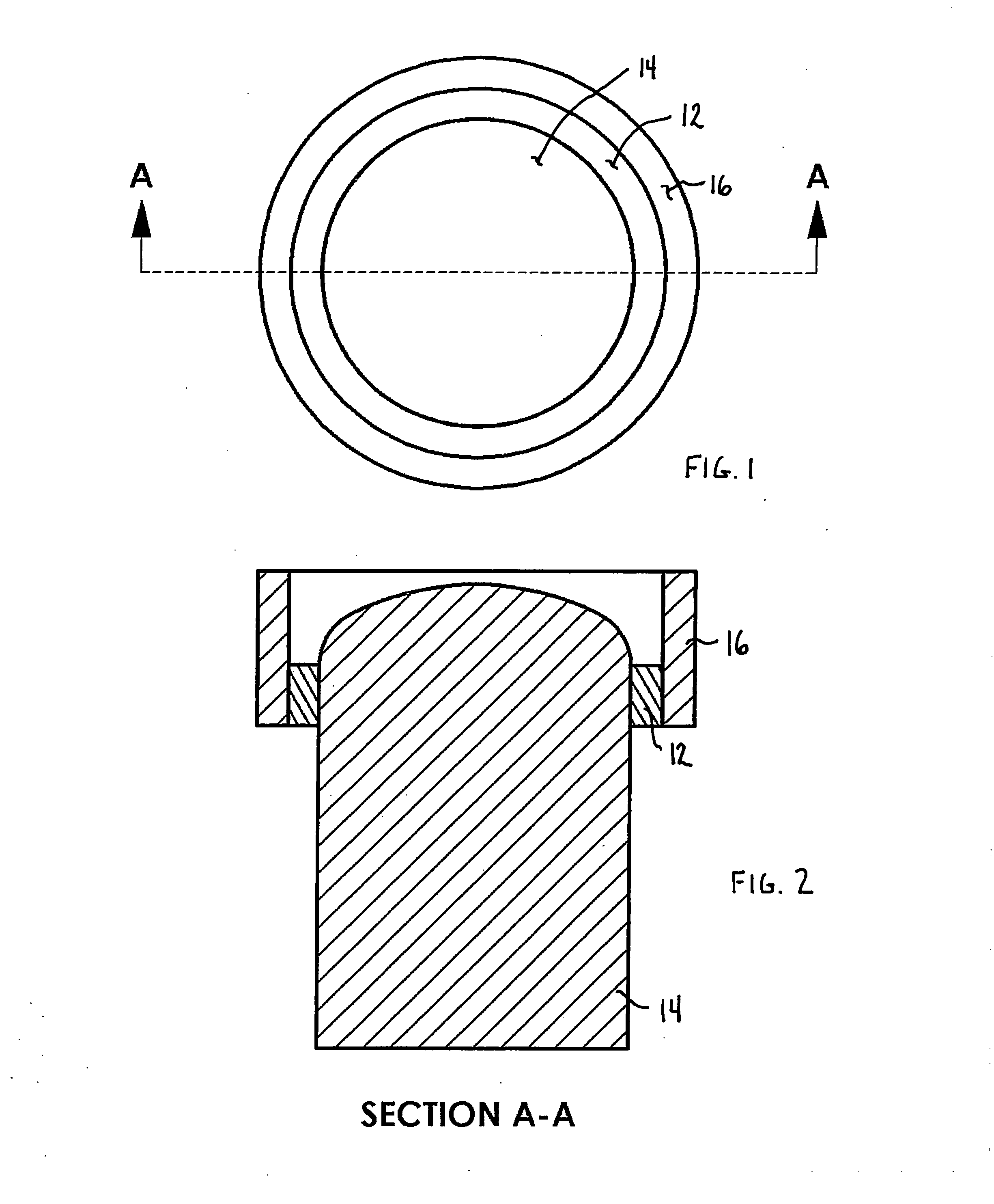
[0035] As shown in FIGS. 1 and 2 and generally referred to as system 10 in FIG. 3, catalytic reactor 12 is positioned in communication with heater head 14, and rigidly held in place by catalyst holder 16. Catalytic reactor 12 comprises catalyst deposited on Microlith® ultra-short-channel-length metal mesh elements. The reactor provides heat transfer to heater head 14 by thermal conduction. Catalyst holder 16 also serves as a heat exchanger with respect to the heat generated by the catalytic reactor 12 and transferred to the gases passing over and in proximity to catalyst holder 16.

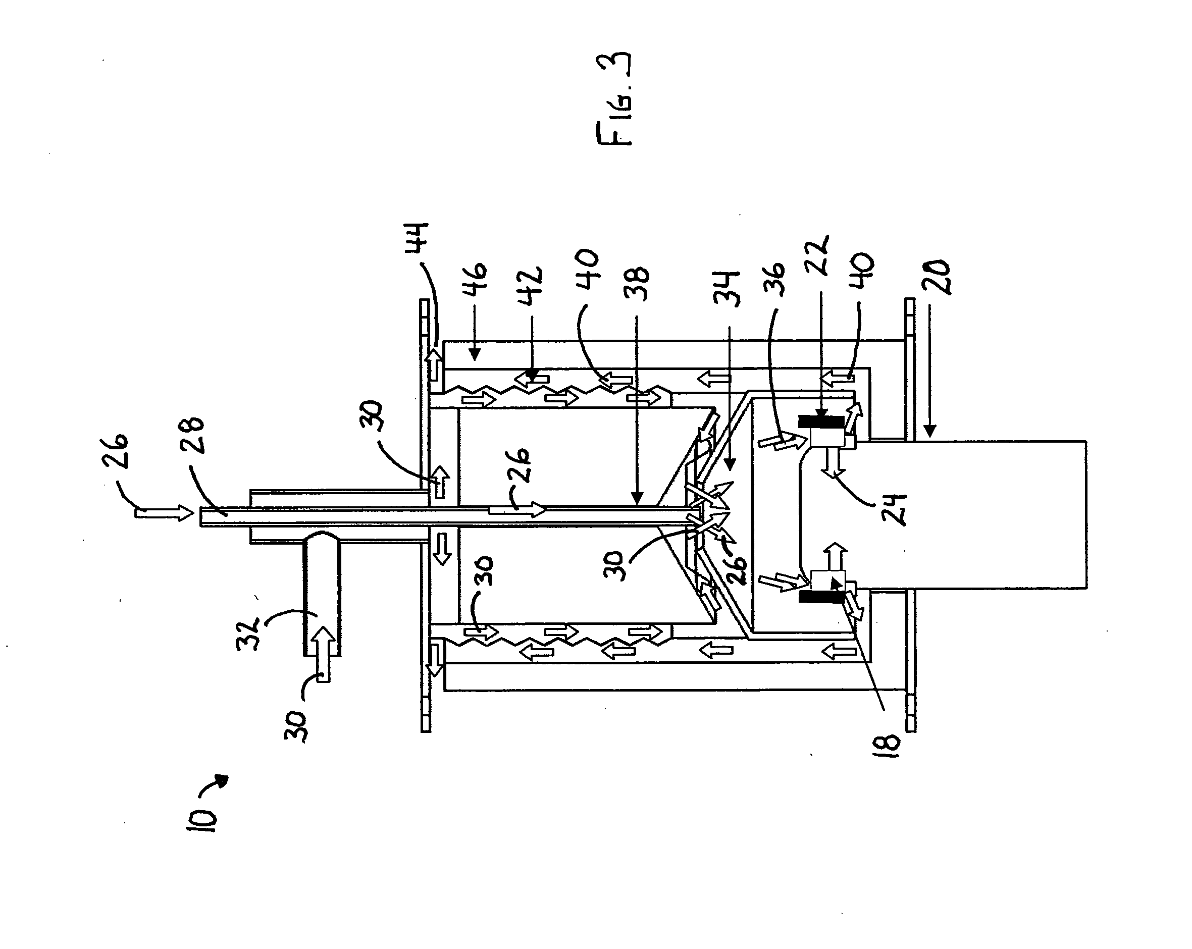
[0036] As depicted in FIGS. 2 and 3, system 10 comprises a catalytic reactor 18 positioned in communication with Stirling Engine heater head 20, and held in place by catalyst holder 22. Catalytic reactor 18 provides heat transfer to heater head 20 by thermal conduction 24 through internal heat acceptor 25. In the embodiment of the invention depicted, fuel 26 is introduced via fuel injection path 28 and ai...


PUM


Abstract

The invention provides a method for transferring heat by conduction to the internal heat acceptor of an external combustion engine. Fuel and air are introduced and mixed to form an air/fuel mixture. The air/fuel mixture is directed into a catalytic reactor that is positioned substantially adjacent to the heater head. Heat is transferred via conduction from the catalytic reactor to the heater head and the catalytic reaction products are exhausted.

Description

CROSS-REFERENCE TO RELATED APPLICATIONS [0001] This application claims the benefit of U.S. Provisional Application No. 60 / 799,857 filed May 13, 2006. This application also is a continuation-in-part of U.S. patent application Ser. No. 11 / 364,402; filed Feb. 28, 2006, incorporated herein by reference.GOVERNMENT RIGHTS [0002] This invention was made with government support under U.S. Contract No. W911-NF-04-1-0238, Subaward No. Y-04-0023. The U.S. government holds certain rights in this invention.FIELD OF THE INVENTION [0003] The present invention is generally directed to an apparatus for providing heat to an external combustion engine. In particular, the present invention is directed toward providing substantially conductive heat transfer to the internal heat acceptor, commonly referred to the heater head, of a Stirling Engine. More particularly, the present invention comprises a burner containing a recuperator, fuel injector, mixer (via swirler), heat transfer arrangement and igniter...

Claims


Application Information

Patent Timeline
IPC IPC(8): F02G1/043
CPCF02G1/043F02G2254/70F02G1/055
Inventor ROYCHOUDHURY, SUBIRSPENCE, DAVID L.CROWDER, BRUCEBERRY, JONATHANMASTANDUNO, RICHARD
Owner PRECISION COMBUSTION
Why Eureka
Try Eureka