Gas turbine combustor

a technology combustor blade, which is applied in the direction of hot gas positive displacement engine plants, combustion process, lighting and heating apparatus, etc., can solve the problems of insufficient shear force of gas turbine combustor, the use of nozzles, etc., to prevent the durability of combustion cylinder deterioration, reduce emissions, and stabilize combustion

Inactive Publication Date: 2014-05-22
IHI POWER SYST CO LTD +1
View PDF5 Cites 2 Cited by
  • Summary
  • Abstract
  • Description
  • Claims
  • Application Information

AI Technical Summary

Benefits of technology

[0012]The gas turbine combustor according to the first aspect is configured so that air flowing inside through the holes formed in the peripheral wall of the premixing tube forms a swirl flow in a cylindrical gap between the peripheral wall and the inner wall so as to be fed into the combustion cylinder. Air and fuel are supplied from one end side of the premixing tube into an inner space of the inner wall, which are formed into a mixture. The mixture forms the uniform straight flow along the axial direction of the inner wall over an entire region inside the inner wall under no influence of interference of the swirl flow, and is supplied into the combustion cylinder for combustion. The straight flow of the mixture in the premixing tube secures the uniform cross section area as the one inside the peripheral wall without any disturbance of the uniform axial flow at the center of the premixing tube owing to intrusion of the air swirl flow through the holes in the peripheral wall of the premixing tube. Therefore, the flame is stably retained at the appropriate position in the combustion cylinder so as to prevent deterioration in durability of the combustion cylinder by the heat and to realize stabilized combustion and low emission.
[0013]The inner wall of the gas turbine combustor according to the second aspect, owing to the effect of the gas turbine combustor according to the first aspect, has the straight cylindrical inner circumferential surface. Compared to the structure with the inner wall having a nozzle-like inner circumference surface protruding inward, the gas turbine combustor according to the invention is configured to suppress adhesion of the fuel supplied from the fuel supply unit to the inner wall. As the inner diameter of the inner wall is kept constant, the flow velocity of the mixture is kept at a constant value adequately to hardly fluctuate, resulting in a steady straight flow.
[0014]The gas turbine combustor according to the third aspect, owing to the effect of the gas turbine combustor according to the second aspect, has the fuel supply unit formed as the pressure injection nozzle of hollow cone type. This makes it possible to inject the fuel in the hollow cone shape, and to atomize the fuel in good condition irrespective of the air flow.
[0015]The gas turbine combustor according to the fourth aspect, owing to the effect of the gas turbine combustor according to the third aspect, is configured so that the other end of the premixing tube protrudes into the combustion cylinder. The fuel injected into the premixing tube is exposed under the high temperature atmosphere in the combustion cylinder so as to promote evaporation.
[0016]The gas turbine combustor according to the fifth aspect, owing to the effect of the gas turbine combustor according to the fourth aspect, is configured to prevent the problem of an increase in the temperature at the other end side of the premixing tube caused by the conically injected fuel through the pressure injection nozzle, which is adhered to the other end of the premixing tube and ignited.
[0017]The gas turbine combustor according to the sixth aspect, owing to the effect of the gas turbine combustor according to the fifth aspect, is configured to suppress the spread of the conically injected fuel through the pressure injection nozzle by the air from the flow channel provided around the pressure injection nozzle. This makes it possible to further alleviate adhesion of the fuel to the inner wall.

Problems solved by technology

However, the aforementioned generally employed gas turbine combustor has a difficulty in stabilization of the flame resulting from the swirl flow supplied inside through the holes formed in the peripheral wall surface of the premixing tube, which intrudes the premixing tube toward the center to disturb uniformity of the axial flow at the center part of the premixing tube.
The nozzle employed in the generally employed gas turbine combustor also has a problem of insufficient shear force to atomize the liquid film of the air blasted fuel fed from the filmer because the straight air flow only exists around the fuel liquid film.

Method used


Image

  • Gas turbine combustor
  • Gas turbine combustor
  • Gas turbine combustor

Examples


Embodiment Construction

[0020]An embodiment of the present invention will be described in detail referring to the drawings.

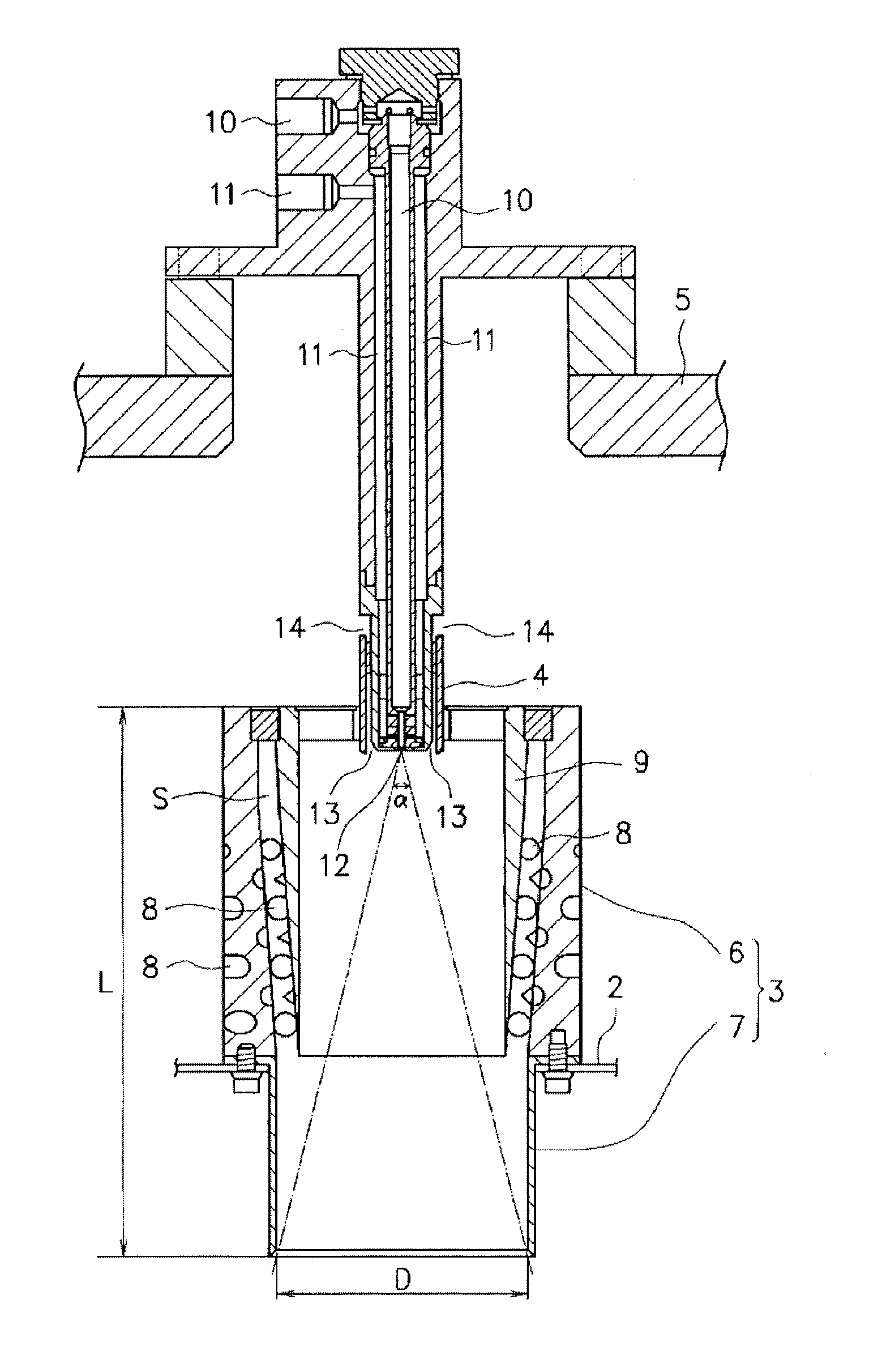
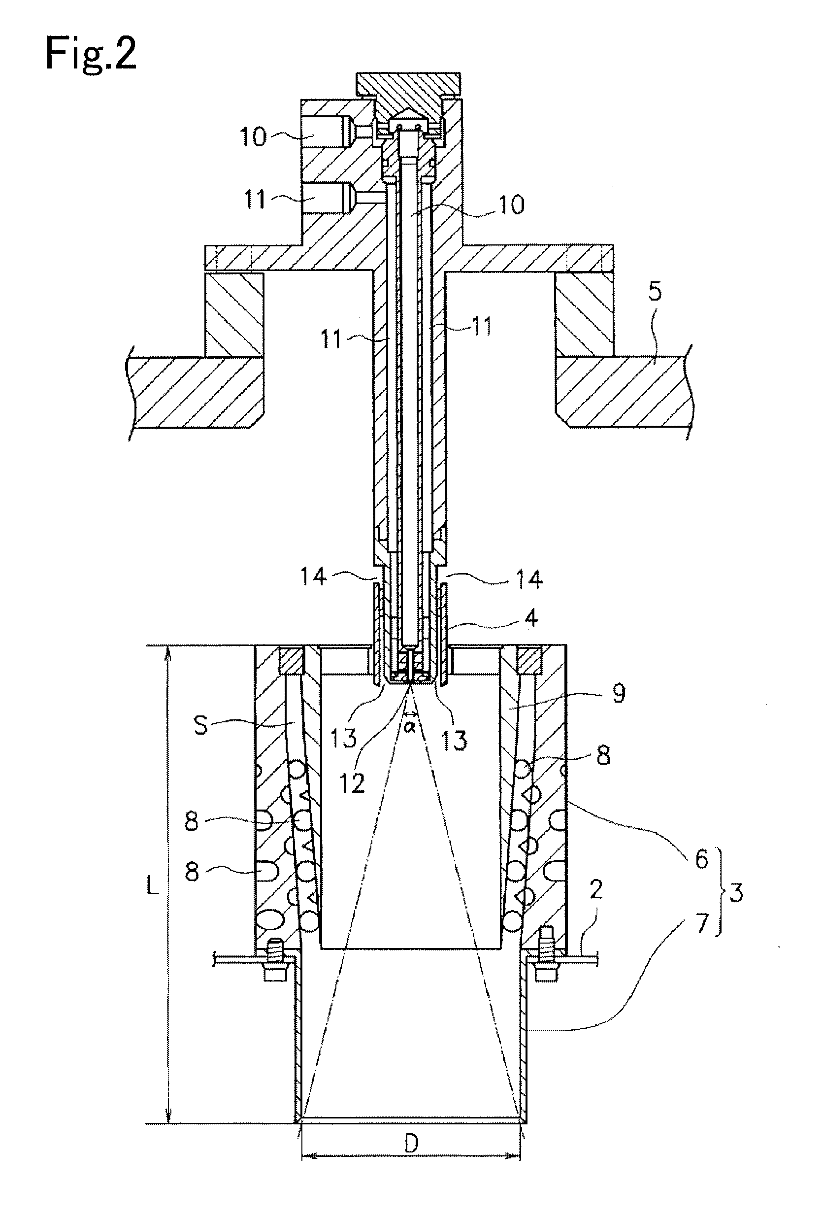
[0021]Referring to FIG. 1, a general structure of a gas turbine combustor 1 according to an embodiment will be described. The gas turbine combustor 1 includes a substantially cylindrical combustion cylinder 2. The combustion cylinder 2 has a top portion closed, and a lower opening communicated with an exhaust side of a not shown gas turbine. The top portion of the combustion cylinder 2 is provided with a premixing tube 3, which will be described in detail later. A top portion of the premixing tube 3 is provided with a pressure injection unit 4 as a fuel supply unit. The combustion cylinder 2 and the premixing tube 3 are encased with an outer cylinder 5 communicated with a compressed air inlet of a turbo-compressor (not shown). A part of a fuel supply system connected to the pressure injection unit 4 is guided to the outside while penetrating the top portion of the outer cylinder 5.

[002...


PUM


Abstract

A gas turbine combustor includes a combustion cylinder, a premixing tube, and a pressure injection unit. Holes are formed in a peripheral wall of the premixing tube in a tangential direction. An inner wall is provided in the peripheral wall while having a gap therefrom. The compressed air in the gap forms a swirl flow. The compressed air and injected fuel supplied into the inner wall form straight flows each with a predetermined cross-section area in the inner wall under no influence of the swirl flow. They are combusted in the combustion cylinder via a protruding wall. The flame is stably retained at an appropriate position apart from the top portion of the combustion cylinder to improve durability without being excessively heated. This may prevent deterioration in durability of the combustion cylinder by the heat by retaining the flame at the appropriate position in the combustion cylinder.

Description

TECHNICAL FIELD[0001]The present invention relates to a gas turbine combustor. More particularly, the present invention relates to a gas turbine combustor configured to generate an air swirl flow inside a premixing tube connected to and communicated with a combustion cylinder, and to secure a region where straight flows of air and fuel are generated so as to prevent deterioration in durability of the combustion cylinder by stably retaining a flame at an appropriate position in the combustion cylinder, and simultaneously, to realize stabilization of combustion and low emission.BACKGROUND ART[0002]Japanese Unexamined Patent Application Publication No. 2009-198054 discloses a gas turbine combustor 1 provided with a combustion cylinder 2, a premixing tube 3, and a fuel supply unit 5. The gas turbine combustor 1 is configured to allow the fuel supply unit to supply the fuel to an annular fuel passage 16 along a tangential direction so that the fuel is uniformly injected through an annula...

Claims


Application Information

Patent Timeline
Patent Type & Authority Applications(United States)
IPC IPC(8): F23R3/28
CPCF23R3/12F23R3/32F23R3/286
Inventor KOYAMA, MASAMICHITACHIBANA, SHIGERU
Owner IHI POWER SYST CO LTD
Why Eureka
Try Eureka