Rendition-based graphical layout management

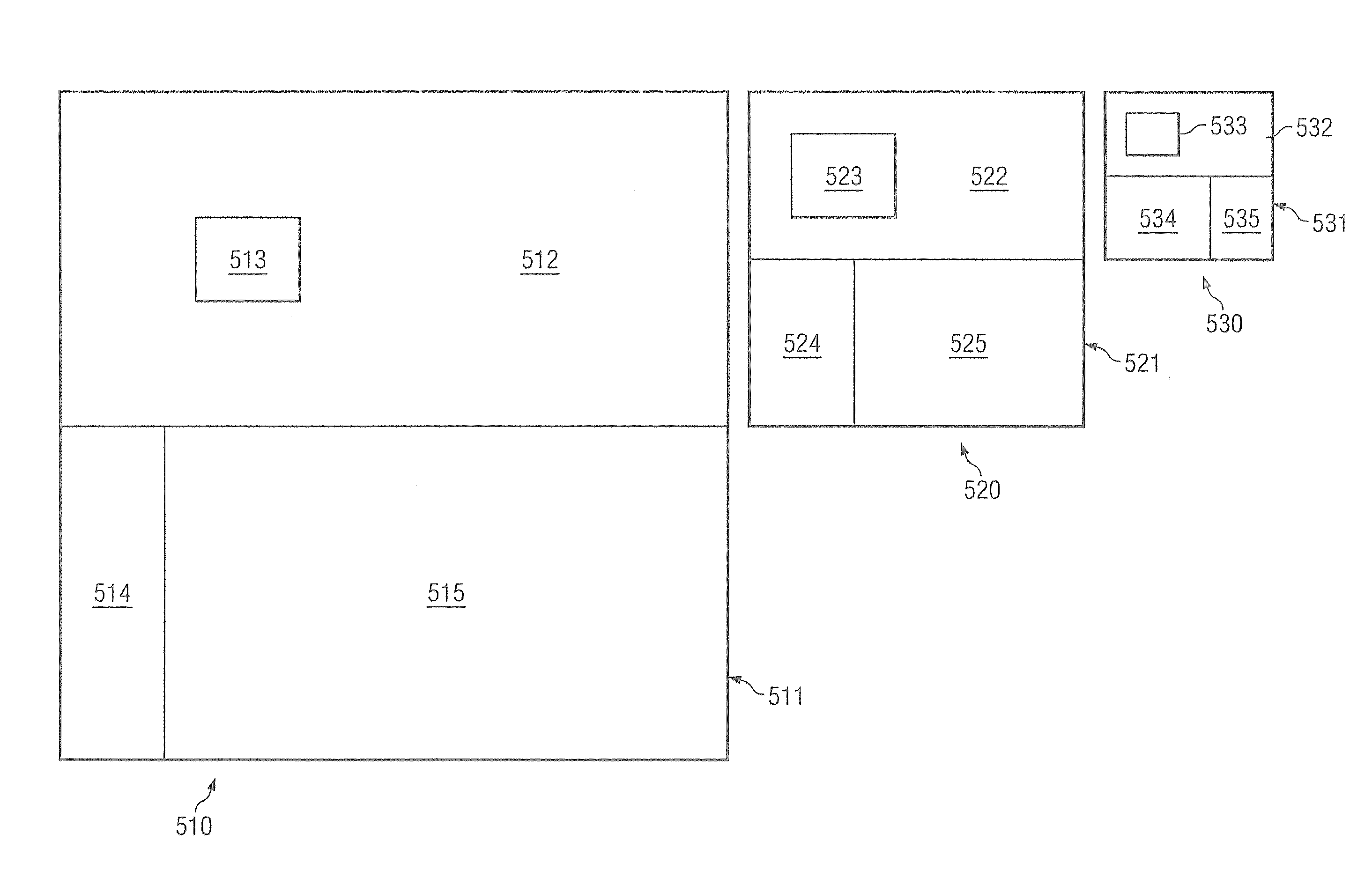
a graphical layout and rendition-based technology, applied in the field of computer program layout, can solve the problems of difficult to develop various program aspects, insufficient display of particular size of window b>100/b> in fig. 1a, and a number of challenges

Active Publication Date: 2010-10-19
ADOBE SYST INC
View PDF4 Cites 28 Cited by
  • Summary
  • Abstract
  • Description
  • Claims
  • Application Information

AI Technical Summary

Benefits of technology

[0013]For example, a designer may utilize a graphical development environment to layout the items, such as control buttons, list boxes, trees, images, and other display objects, within a graphical image or other rendition (first constraint image) of a program's user interface window, wherein the window is of a first (e.g., small) size. Thereafter, the designer may utilize the graphical development environment to layout the items within a graphical image or other rendition (second constraint image) of the program's user interface window of a different size (e.g., larger). The graphical layouts defined by the designer preferably establish constraints with respect to the resizing of the items within the user interface window, not only at the points specifically defined by the designer but also at points between and / or beyond the expressly defined points. Operation of embodiments of the present teachings provides interpolation between graphical layouts defined by the designer to dynamically generate user interface windows sized between the graphical images provided by the designer. Additionally or alternatively, embodiments of the teachings provide extrapolation for sizes beyond those of the graphical layouts defined by the designer to dynamically generate user interface windows sized larger and / or smaller than the graphical images provided by the designer. Accordingly, the designer may visually create the user interface layout to create a desired appearance throughout a range of window sizes without the need to delve into relative sizes, proportions, or hierarchies of the various items in the window.

Problems solved by technology

The programmer, on the other hand, typically possesses education and experience more directed to the sciences than to the arts, giving this individual unique talents in developing efficient and stable programming code, although perhaps being limited in ability with respect to presenting visually pleasing, ergonomically designed, and / or intuitive user interfaces.
However, various aspects of program development continue to require specialized talents, or are otherwise less simple to develop various program aspects than may be desirable.
Object sizing and placement when a program user interface window is resized is an example of one program aspect which is often problematic in program development.
The particular size of window 100 in FIG. 1A may be insufficient to display all items associated with the menus, boxes, and / or panels thereof.
However, accommodating resizing of windows presents a number of challenges with respect to developing programs that may not be sufficiently addressed without the special talents of individuals involved in the program's development.
Describing how each of these items of window 100, even ignoring issues with respect to resizing objects within these items, are to be treated in a resizing operation is complicated for a sophisticated developer and may be beyond the skill level of some designers.
Although it is possible to prohibit the resizing of windows, such as is often done with respect to certain dialog boxes, such a prohibition is typically not an acceptable solution when developing robust applications having a flexible user interface.
Such a solution is very code oriented, not very declarative, and not very graphical.
Accordingly, certain individuals, such as designers, may not readily adopt such a solution.
Particular individuals, particularly those which are visually oriented, have difficulty conceptualizing such a hierarchy and typically do not think in relative sizes.
Accordingly, the foregoing solution may not present an optimal solution for layout of a user interface by many individuals.

Method used


Image

  • Rendition-based graphical layout management
  • Rendition-based graphical layout management
  • Rendition-based graphical layout management

Examples


Embodiment Construction

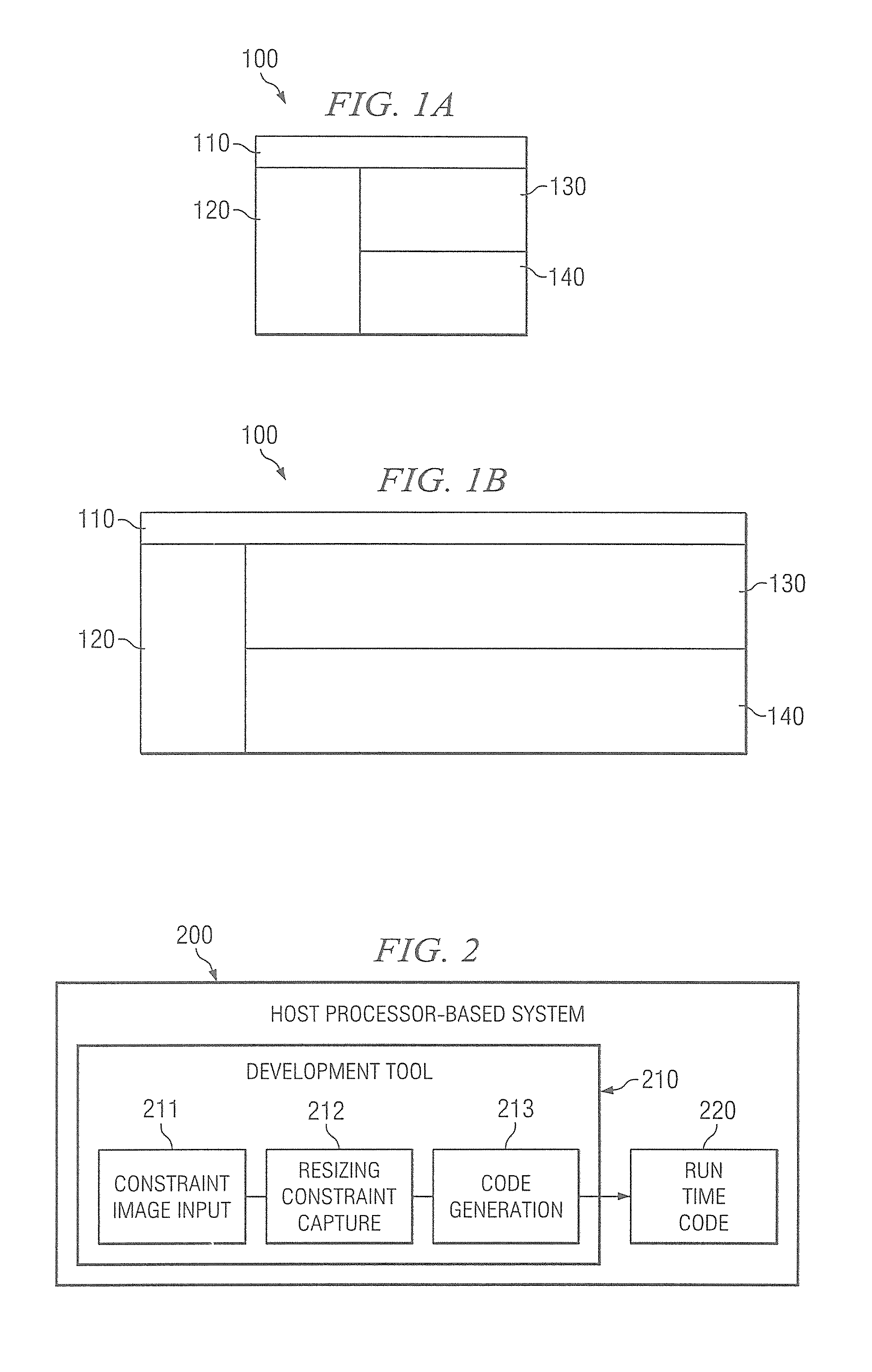
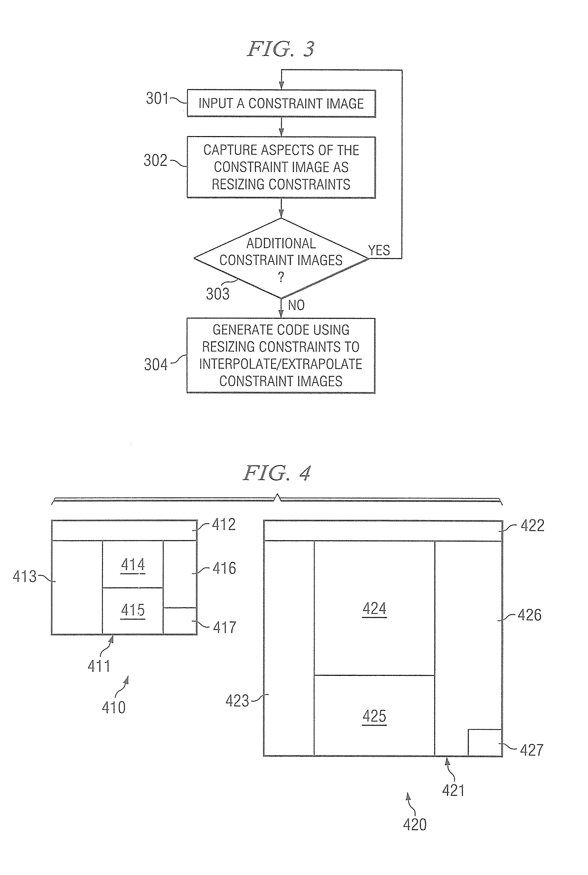
[0023]Directing attention to FIG. 2, a system adapted to provide rendition-based graphical layout management according to an embodiment of the present teachings is shown. The embodiment illustrated in FIG. 2 includes development tool 210, such as may comprise an instruction set operable upon host processor-based system 200 to define operation as described herein, providing a graphical development environment useful in developing computer programs. Accordingly, when implemented in software, elements of the present teachings are essentially the code segments to perform the described tasks. The program or code segments can be stored in a computer readable medium or transmitted by a computer data signal embodied in a carrier wave, or a signal modulated by a carrier, over a transmission medium. The “computer readable medium” may include any medium that can store information. Examples of the computer readable medium include an electronic circuit, a semiconductor memory device, a ROM, a fl...


PUM


Abstract

Systems and methods which implement rendition-based graphical layout management techniques are shown. According to an embodiment, desired resizing of items within a program's user interface is managed through a developer graphically describing a plurality of different sized renditions of a desired user interface and other different sized renditions of the user interface being dynamically interpolated and / or extrapolated through operation of the program. According to embodiments, linear interpolation and / or extrapolation is provided with respect to windows sized differently than constraint images provided by a developer. In embodiments where more than two constraint images are provided, piece-wise liner interpolation and / or extrapolation may be provided. Non-linear interpolation and / or extrapolation may be implemented according to embodiments of the present teachings.

Description

CROSS-REFERENCE TO RELATED APPLICATIONS[0001]This application is a continuation of U.S. patent application Ser. No. 11 / 172,422 filed Jun. 30, 2005 and entitled “RENDITION-BASED GRAPHICAL LAYOUT MANAGEMENT.” the disclosure of which is hereby incorporated herein by reference.TECHNICAL FIELD[0002]The present disclosure relates generally to computer program layout and, more particularly, to user interface layout using rendition-based graphical layout management.BACKGROUND[0003]Computer program development, such as development of web based applications, WINDOWS based applications, et cetera, often requires the talents of several specialized individuals. For example, one or more designers (e.g., a visual designer and an interaction designer) may be utilized to provide layout of an application program's user interface in order to provide a visually pleasing, ergonomically designed, intuitive, and / or efficient user interface. The designer may determine where control buttons, list boxes, tre...

Claims


Application Information

Patent Timeline
Patent Type & Authority Patents(United States)
IPC IPC(8): G06F13/00G06F15/00
CPCG06F3/0481G06T11/60
Inventor SMITH, ALBERT GORDON
Owner ADOBE SYST INC
Why Eureka
Try Eureka