Method and system for determining plunger location in a plunger lift system

a technology of plunger lift and plunger location, which is applied in the field of plunger lift system, can solve the problems of affecting the operation of the plunger lift system

Inactive Publication Date: 2010-10-26
HARBISON FISCHER
View PDF8 Cites 57 Cited by
  • Summary
  • Abstract
  • Description
  • Claims
  • Application Information

AI Technical Summary

Problems solved by technology

The amount of liquid produced in many wells is insufficient to warrant a pump.
Not only is this inefficient, but the plunger's rise speed may be too fast, damaging both itself and equipment at the top of the wellhead.
However, a shut-in well loses production.
However, some published estimates have been proven to be significantly inaccurate when measured with acoustic test equipment, such as that manufactured by

Method used


Image

  • Method and system for determining plunger location in a plunger lift system
  • Method and system for determining plunger location in a plunger lift system
  • Method and system for determining plunger location in a plunger lift system

Examples


Embodiment Construction

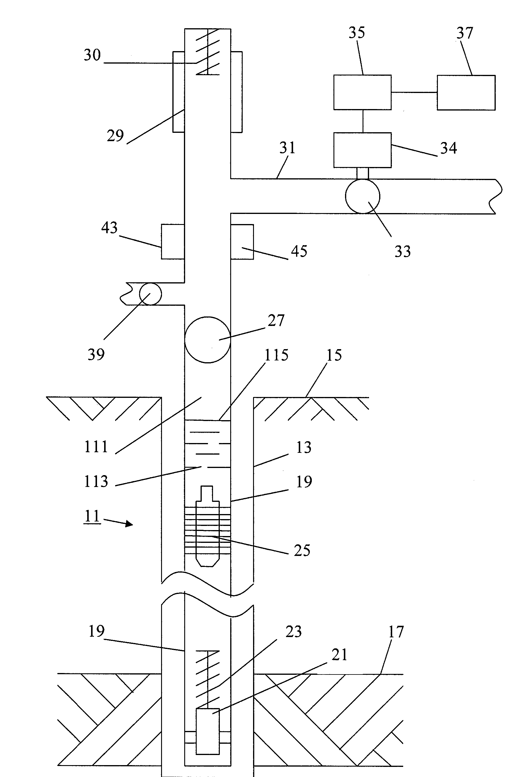
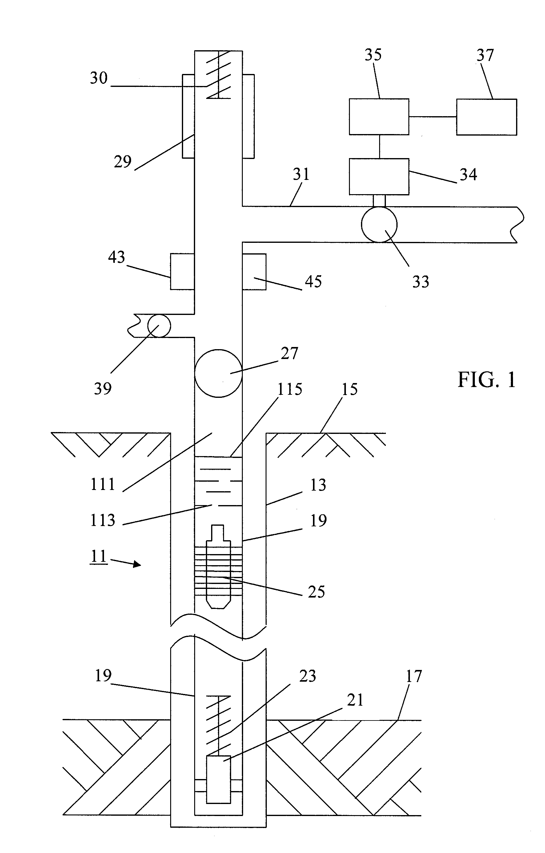
[0035]The present invention provides a plunger lift system with an energy source on the plunger. The energy source allows the movement of the plunger in the well to be tracked or monitored and allows the liquid level in the tubing to be detected.

[0036]A typical well 11 is shown in FIG. 1. The well has casing 13 that extends from the surface 15 down to the producing formation 17 or zone. A string of tubing 19 is located in the casing. At or near the bottom end of the tubing 19, there is a seating nipple 21 or tubing stop. Located above the seating nipple 21 is a bottom hole bumper spring 23. The bumper spring 23 can be provided with a standing valve, which valve prevents liquid from exiting the tubing and returning to the formation such as may occur when the plunger is falling through the liquid. A plunger 25 is provided to travel inside of the tubing 19.

[0037]Wellhead equipment at the surface caps the top of the casing. Various valves are provided, such as a master valve 27, which i...


PUM


Abstract

A plunger has a transmitter that produces signals as the plunger moves in a well. The signals are pulses that are produced at a constant interval. The plunger signals are detected and used to determine the location, direction of travel and speed of the plunger in the well. In addition, the location or height of the liquid level is detected as is the arrival of the plunger at the well bottom.

Description

[0001]This application claims the benefit of U.S. patent application Ser. No. 60 / 811,212, filed Jun. 6, 2006.FIELD OF THE INVENTION[0002]The present invention relates to plunger lift systems in producing wells, such as gas wells.BACKGROUND OF THE INVENTION[0003]In wells that produce both natural gas and oil, the gas and oil exit the formation and enter the perforated casing and tubing string that is located inside of the casing. The gas may flow up the casing or the tubing string, while oil and other liquids travel through the tubing string to the wellhead at the surface. The oil and other liquid are forced to the surface by way of either natural formation pressure or by artificial lifting mechanisms, such as pumps.[0004]For wells whose primary purpose is to produce gas, the presence of liquid at the bottom of the well bore adds backpressure to the formation, and thus inhibits the free flow of natural gas through the well bore to the surface. It has been estimated that 80% of the na...

Claims


Application Information

Patent Timeline
IPC IPC(8): E21B47/04E21B47/09
CPCE21B43/121E21B47/09E21B47/095
Inventor COSBY, DAVID D.
Owner HARBISON FISCHER
Why Eureka
Try Eureka