
Hybrid heater

a heater and hybrid technology, applied in the field of heaters, can solve the problems of unsatisfactory temperature spike, temperature drop at the heater outlet, and mass heaters are typically slow to respond to flow changes, and achieve stable temperature control, superior heat transfer, and minimize or eliminate the effect of associated disadvantages

Active Publication Date: 2010-10-26
GRACO INC
View PDF29 Cites 26 Cited by
  • Summary
  • Abstract
  • Description
  • Claims
  • Application Information

AI Technical Summary

Benefits of technology

The invention is a hybrid heater that combines the benefits of mass style and direct contact style heaters. It includes a structural mass with passages for a heater rod, providing stable temperature control and superior heat transfer. The hybrid heater is also faster to warm up and has a lower cost of manufacture. A coiled spring or other spiral arrangement provides flow uniformity and reduces backpressure. A temperature sensor can maintain stable temperature control, and a mass sleeve protects the sensor during transitions. Overall, the hybrid heater design provides improved performance and efficiency.

Problems solved by technology

During the transition from the dynamic mode to the static mode, however, the mass ends to retain its temperature and pass it off to the static chemical causing an undesirable temperature spike.
Conversely, as the chemical transitions from the static mode to the dynamic, the inefficiency of the mass heater causes a temperature drop at the outlet of the heater.
Thus, mass style heaters are typically slow in responding to flow changes.
Direct style heaters provide a much greater difference in temperature between the set point temperature and the fire rod surface temperature such that the temperature control is less stable in steady conditions than mass style heaters.
Further, direct contact heaters have historically been more costly to manufacture and assemble than mass style heaters.
Moreover, the physical dimensions of direct style heaters constrain the number of tubes, thus shortening the contact surface area available for heat transfer.

Method used


Image

  • Hybrid heater
  • Hybrid heater
  • Hybrid heater

Examples


Embodiment Construction

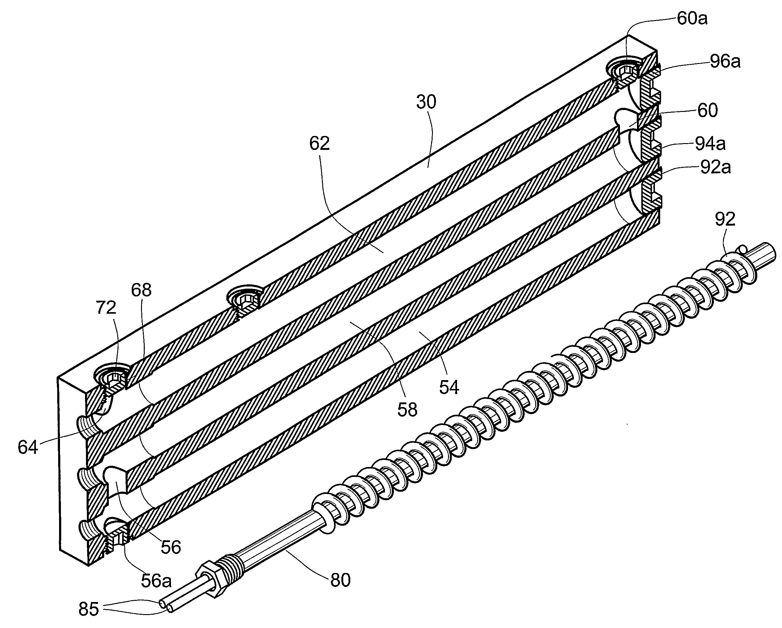
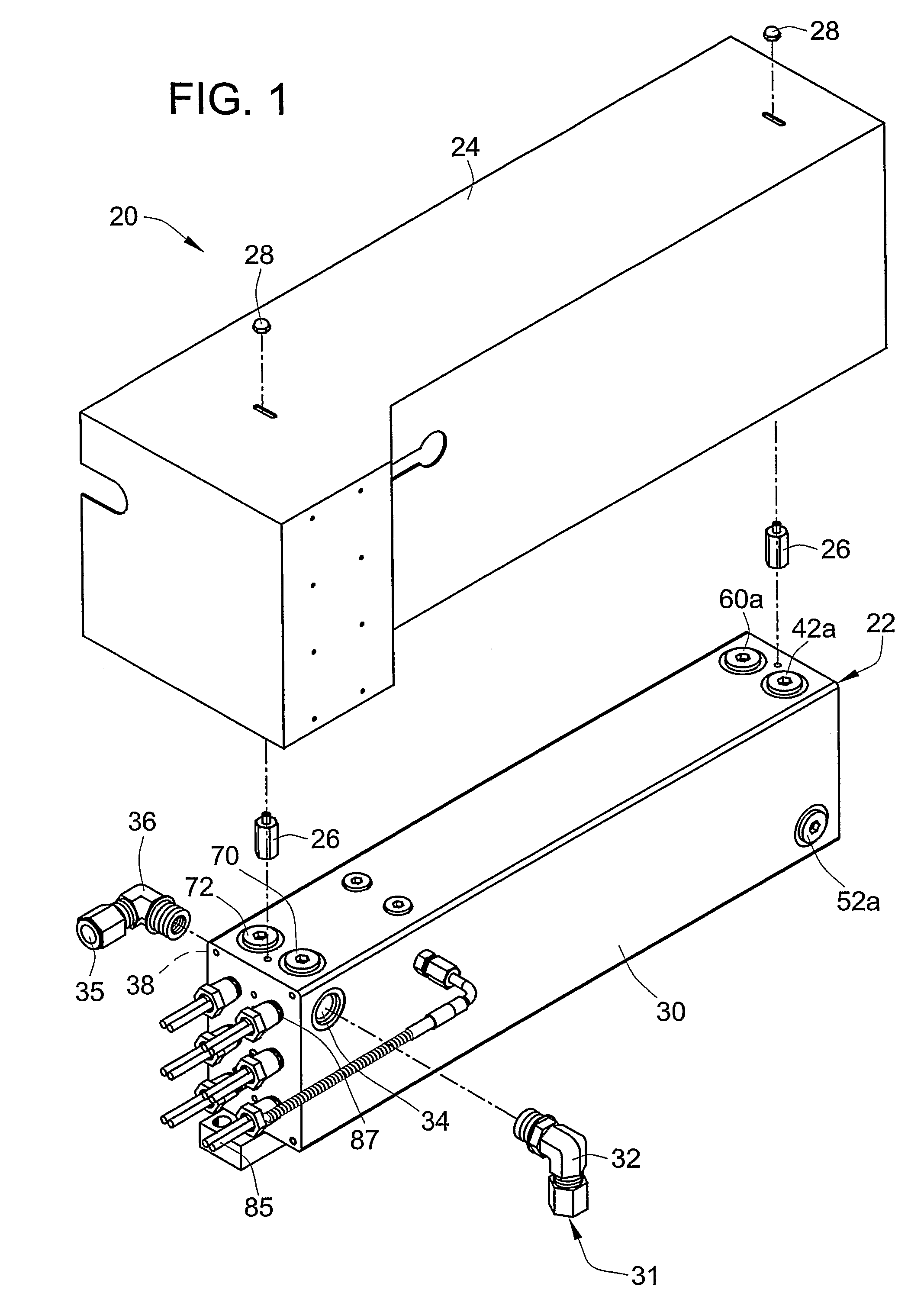
[0024]Turning now to the drawings, there is shown in FIG. 1, a preheater assembly 20 constructed in accordance with teachings of the invention. The preheater assembly 20 includes a preheater 22, which is covered by a preheater cover 24. In the embodiment shown, the preheater cover 24 is spaced apart from the preheater 22 by spacers or standoffs 26 and secured by acorn nuts 28, although any appropriate arrangement may be utilized. The preheater 22 comprises a structural mass or block 30 that is preferably formed of aluminum or the like. The structural mass 30 may be formed by any appropriate method, but is preferably machined from a block of aluminum.

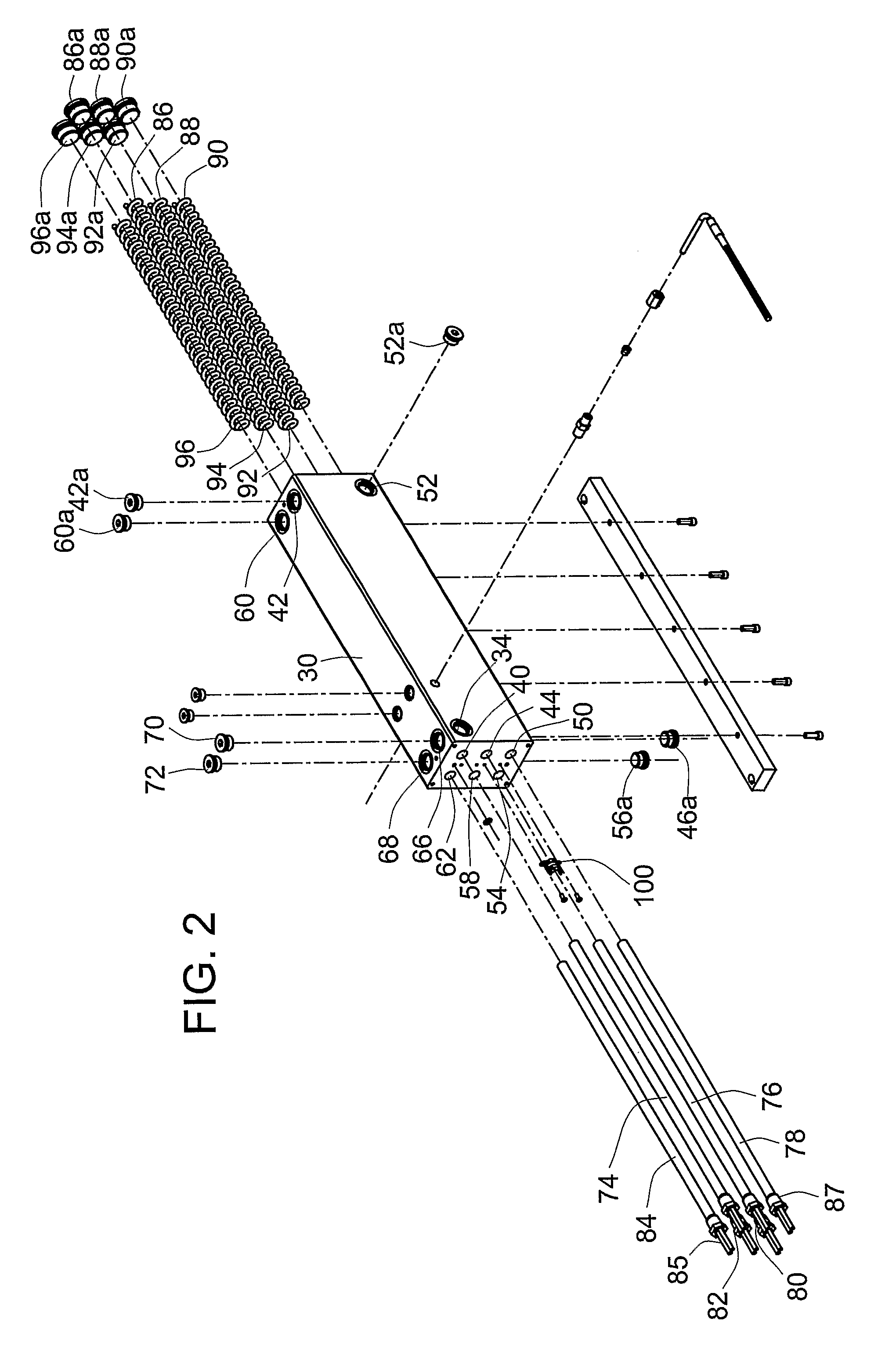
[0025]In order to provide a flow of material to be heated, the preheater 22 is provided with an inlet 35 in the form of an inlet fitting 36 disposed in an inlet bore 38 in the mass 30, and an outlet 31 in the form of an outlet fitting 32 disposed in an outlet bore 34 in the mass 30. Internally, the mass 30 is provided with a series of pa...


PUM

PropertyMeasurementUnit
surface temperatureaaaaaaaaaa
volumeaaaaaaaaaa
structural massaaaaaaaaaa

Abstract

A hybrid heater that includes a structural mass into which passages are provided to create a labyrinth for chemical flow through the structural mass, the passages being sized and disposed to receive a plurality of heater rods such that the chemical is traversed through the passages in direct contact with the heater rods. A coiled spring may be disposed or other spiral arrangement provided in the space between and against the walls of the passages and the heater rod to facilitate flow uniformity around the rods. A temperature sensor may be provided in direct contact with the heating element and may be fitted with a mass sleeve to draw off any excess heat on the sensor during transitions.

Description

FIELD OF THE INVENTION[0001]This invention pertains to dedicated heaters for preheating chemical in mixing heads or spray guns for use in chemical processing, and more particularly to a heating unit that combines the beneficial features of both mass and direct contact style heaters.BACKGROUND OF THE INVENTION[0002]In chemical processing, such as plural component polyurethane processing, the proper mixing of the chemical components is essential to developing the final physical properties specified by the system supplier. In impingement designed mixing heads or spray guns, lowering the viscosities with heat helps to facilitate proper mixing. The two types of preheaters are typically utilized in impingement designed mixing heads / spray guns.[0003]The first style, mass style, heats by conduction. Mass style heating utilizes a structural block, which is typically aluminum, into which holes are bored or small grooves cut and hydraulically connected to form a labyrinth through which the che...

Claims


Application Information

Patent Timeline
Patent Type & Authority Patents(United States)
IPC IPC(8): F24H1/10
CPCF24H1/102Y10T29/49833F24H1/00F24H1/10
Inventor COMMETTE, DENIS S.PRIEST, JEROME
Owner GRACO INC
Learn More