Controlling access to an area

a control and access technology, applied in the field of control of can solve the problems of difficult to retrieve the physical keys issued to former employees, cumbersome management of doors with traditional locks and keys, and inability to control access to an area,

Inactive Publication Date: 2010-10-26
ASSA ABLOY AB
View PDF204 Cites 62 Cited by
  • Summary
  • Abstract
  • Description
  • Claims
  • Application Information

AI Technical Summary

Problems solved by technology

Traditional doors and walls may be used for protection of sensitive areas, but doors with traditional locks and keys may be cumbersome to manage in a setting with many users.
For instance, once an employee is fired, it may be difficult to retrieve the physical keys the former employee was issued while employed.
Moreover, there may be a danger that copies of such keys were made and never surrendered.
Traditional access control mechanisms suffer from many drawbacks.
Fully connected doors may be very expensive.
The cost of running a secure pipe to a distant smart door may vastly exceed the cost of the smart door itself.
Protecting a wire cryptographically, while possibly cheaper, still has its own costs (e.g., those of protecting and managing cryptographic keys).
Moreover, cryptography without steel pipes and security guards cannot prevent a wire from being cut, in which case the no-longer-connected door may be forced to choose between two extreme alternatives: namely, remaining always closed or always open, neither of which may be desirable.
In any case, fully connecting a door is often not a viable option.
However, traditional approaches to smart doors have their own problem.
Therefore, it would be necessary to “deprogram” the PINs of terminated employees, which is difficult for disconnected doors.
Indeed, such a procedure may be very cumbersome and costly: an airport facility may have hundreds of doors, and dispatching a special team of workers to go out and deprogram all of such doors whenever an employee leaves or is terminated may be too impractical.
As demonstrated, disconnected smart doors and cards do not by themselves guarantee the security, convenience and low cost of the access-control system.

Method used


Image

  • Controlling access to an area
  • Controlling access to an area
  • Controlling access to an area

Examples


Embodiment Construction

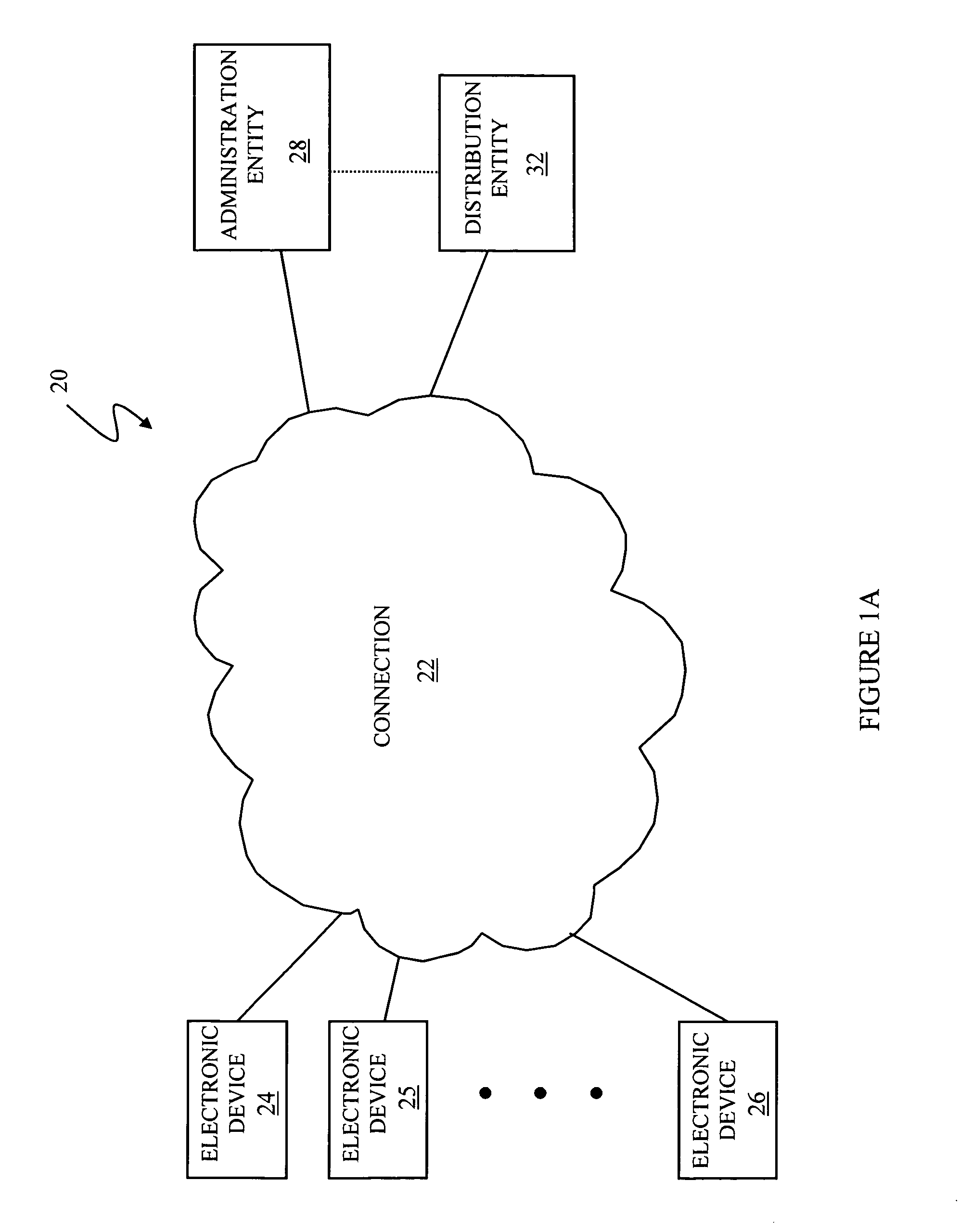
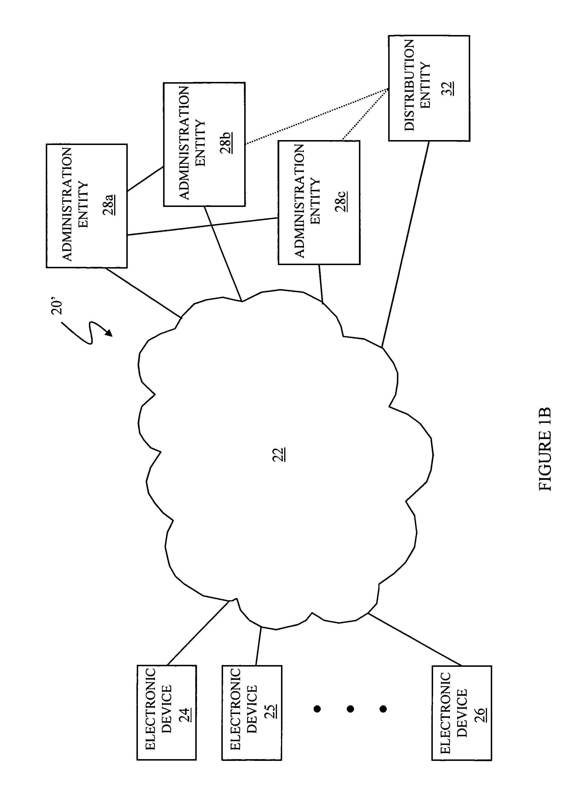
[0032]Referring to FIG. 1A, a diagram 20 illustrates a general connection 22 having a plurality of electronic devices 24-26 coupled thereto. Although the diagram 20 shows three electronic devices 24-26, the system described herein may work with any number of electronic devices. The connection 22 may be implemented by a direct electronic data connection, a connection through telephone lines, a LAN, a WAN, the Internet, a virtual private network, or any other mechanism for providing data communication. The electronic devices 24-26 may represent one or more laptop computers, desktop computers (in an office or at an employees home or other location), PDA's, cellular telephones, disk drives, mass storage devices, or any other electronic devices in which it may be useful to restrict access thereto. In an embodiment herein, the electronic devices 24-26 represent desktop or laptop computers that are used by employees of an organization that wishes to restrict access thereto in case a user / e...


PUM


Abstract

Controlling access includes providing a barrier to access that includes a controller that selectively allows access, at least one administration entity generating credentials / proofs, wherein no valid proofs are determinable given only the credentials and values for expired proofs, the controller receiving the credentials / proofs, the controller determining if access is presently authorized, and, if access is presently authorized, the controller allowing access. The credentials / proofs may be in one part or may be in separate parts. There may be a first administration entity that generates the credentials and other administration entities that generate proofs. The first administration entity may also generate proofs or the first administration entity may not generate proofs. The credentials may correspond to a digital certificate that includes a final value that is a result of applying a one way function to a first one of the proofs.

Description

CROSS-REFERENCE TO RELATED APPLICATIONS[0001]This application claims priority to U.S. provisional patent application No. 60 / 488,645 filed on Jul. 18, 2003, which is incorporated by reference herein, and claims priority to U.S. provisional patent application No. 60 / 505,640 filed on Sep. 24, 2003, which is incorporated by reference herein, and is a continuation-in-part of U.S. patent application Ser. No. 10 / 876,275 filed on Jun. 24, 2004 (pending) which claims priority to U.S. provisional patent application No. 60 / 482,179 filed on Jun. 24, 2003, and which is a continuation-in-part of U.S. patent application Ser. No. 09 / 915,180 filed on Jul. 25, 2001, now U.S. Pat. No. 6,766,450 which is a continuation of U.S. patent application Ser. No. 09 / 483,125 filed Jan. 14, 2000 (now U.S. Pat. No. 6,292,893), which is a continuation of U.S. patent application Ser. No. 09 / 356,745 filed Jul. 19, 1999 (abandoned), which is a continuation of U.S. patent application Ser. No. 08 / 823,354 filed Mar. 24, ...

Claims


Application Information

Patent Timeline
Patent Type & Authority Patents(United States)
IPC IPC(8): H04K1/00G06F21/00H04L9/32
CPCG07C9/00007G07C9/00103G07C9/20G07C9/27
Inventor LIBIN, PHILMICALI, SILVIOENGBERG, DAVID
Owner ASSA ABLOY AB
Why Eureka
Try Eureka