Pseudo public key encryption

a public key and encryption technology, applied in the field of public key encryption, can solve the problems of high cost of calculation, high cost of operation, and high cost of computation required for rsa cryptography with a large bit number, and achieve the effect of low cost and low cos

Inactive Publication Date: 2007-08-16
IBM CORP
View PDF0 Cites 35 Cited by
  • Summary
  • Abstract
  • Description
  • Claims
  • Application Information

AI Technical Summary

Benefits of technology

[0008] According to the present invention, a secret key cryptosystem and tamper-proof hardware are used to realize a pseudo public key cryptosystem at a low cost. A trap-door one-way function, which is considered essential for constitution of a public key cryptosystem generally, requires an “expensive” operation. Such a function is substantially realized with the use of tamper-proof hardware. Each user performs communication using equipment provided with hardware having the same capabilities described below. Such hardware retains association between an ID and a key. In response to a request from a user, the hardware issues and stores an ID, and it can perform decryption and generation of a message authentication code (hereinafter referred to as a MAC) with a key associated with the ID. Though this hardware can perform encryption and verification of a MAC with any given ID, it cannot perform decryption and generation of a MAC. A user publishes h

Problems solved by technology

An algorithm for realizing a public key cryptosystem generally requires a very high cost of calculation.
The RSA cryptography requires an operation of raising a plaintext or a cipher text to the power of the number (an encryption exponent or a decryption exponent) obtained from a value of the Eulerian function of n, which is a product of two large prime numbers and then determining the residue of n, and the cost of this operation is very high.
However, the cost of calculation required for RSA cryptography with a large bit number is very high.
Though measures such as performing such an operation with dedicated hardware may be taken to seek a high speed, this may impose a development and manufacture cost burden or affect product flexibility.
Because of such a situati

Method used


Image

  • Pseudo public key encryption
  • Pseudo public key encryption
  • Pseudo public key encryption

Examples


embodiment 1

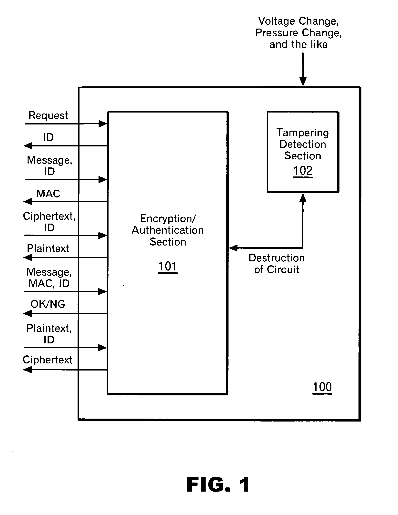
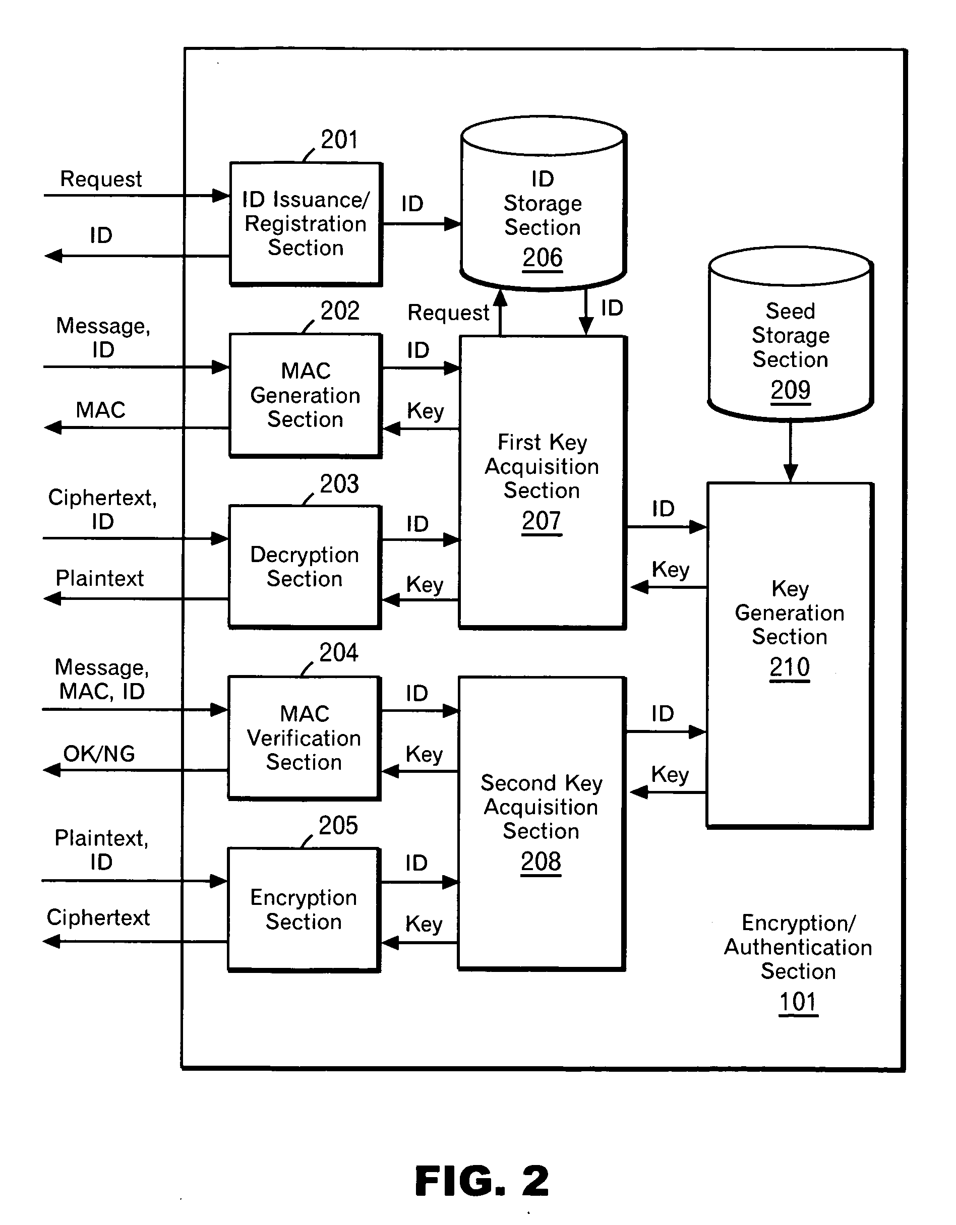
[0060] Description will be made on an embodiment in the case where a sufficient number of keys can be stored in the system 100 (including each interface and sending-receiving protocols) with the use of FIG. 3. It is assumed that a user A and a user B communicate with each other using the system 100 in FIG. 1 (hardware A and hardware B). It is also assumed that a sufficient number of keys are stored in the system 100, each of which is given an ID specific thereto. If the pieces of hardware are the same, mapping of the ID and the key is also the same.

[0061] The user A requests an ID from the hardware A (310). The hardware A selects an ID (hereinafter referred to as ID-A) at random from an ID space (320), and returns the ID to the user A. The ID is also stored in an ID storage section. The user A publishes the ID-A. Meanwhile, the user B has also performed the same processing as the user A. That is, the user B requests an ID from the hardware B (310). The hardware B selects an ID (her...

embodiment 2

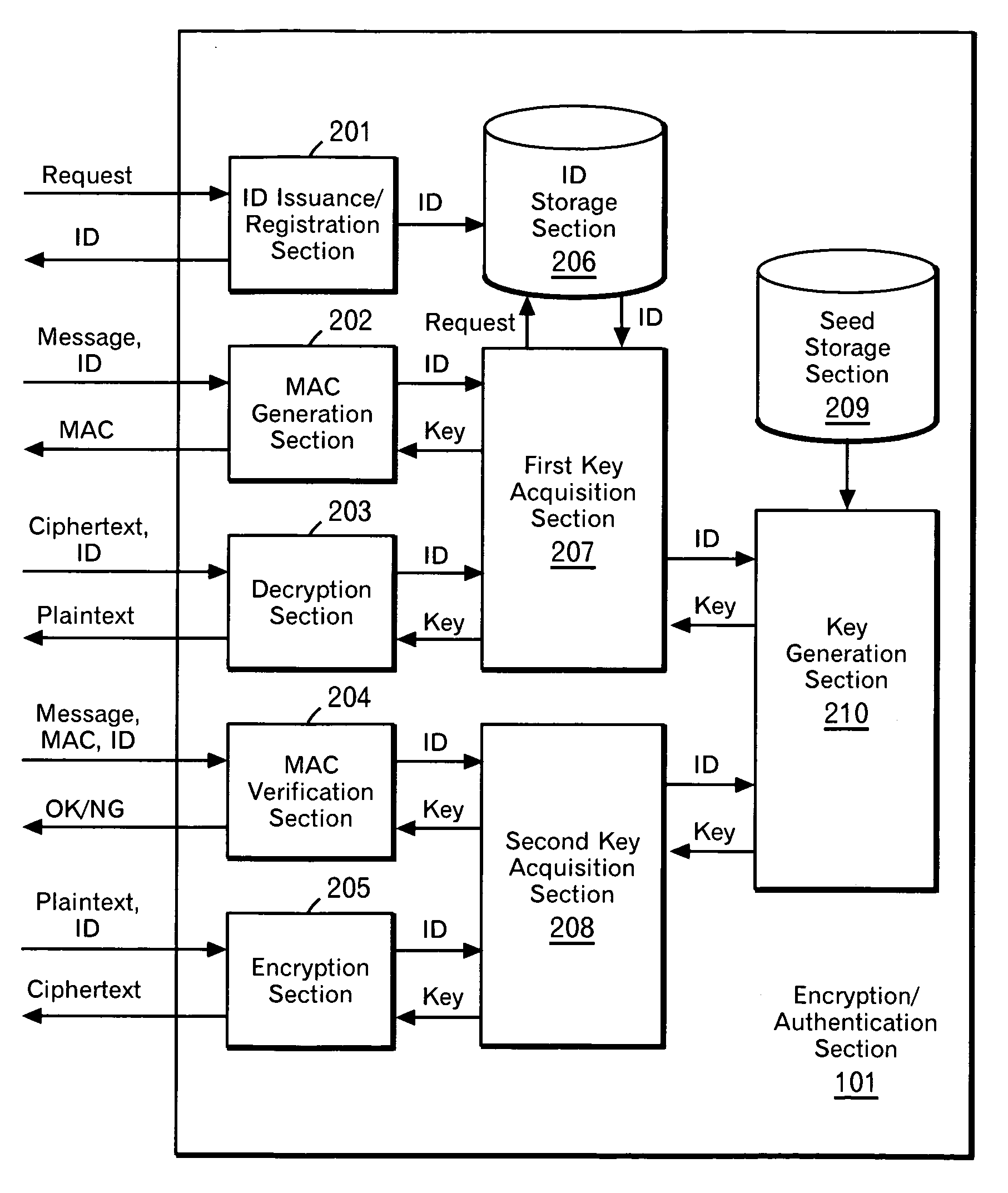
[0064] Actually, it is often impossible to a storage capacity enough to store a sufficient number of key. Description will be made on an embodiment in the case where a sufficient number of keys cannot be stored in the system 100 with the use of FIG. 4. Only one value (hereinafter referred to as a seed) is stored in the system 100 so that a key is generated from the seed and an ID as appropriate. Any hash algorithm (for example, SHA-1) is used so that a hash value of (ID|seed) is used as a key. In this case, the procedure for the user A to create a message to be sent is as follows.

[0065] The procedure from the step where the users A and B request an ID and the hardware selects and stores an ID to the step where each user publishes his own ID is the same as that of the embodiment described above. Suppose that the user A sends a message to the user B. When creating a message to be sent, the user A hands over the message and the ID-A to the hardware A and requests generation of a MAC. ...

embodiment 3

[0067] In the two embodiments described above, there is shown a case where an ID is selected at random. Next, an example of applying the present invention to an ID-based cryptosystem with the use of FIG. 5. In this case, the processing to be performed by the user A in advance is as follows. The user A hands over the hardware A and the ID-A to an ID storage body 520, and requests storage of the ID in the hardware (510). The ID storage body hands over the ID-A to the hardware A, and requests storage of the ID. The hardware A stores the ID-A in the ID storage section. The processing to be performed by the user B in advance is the same. That is, the user B hands over the hardware B and the ID-B to the ID storage body 520, and requests storage of the ID in the hardware (510). The ID storage body hands over the ID-B to the hardware B, and requests storage of the ID. The hardware B stores the ID-B in the ID storage section. The procedure for the user A to create a message to be sent and th...


PUM


Abstract

According to the present invention, a secret key cryptosystem and tamper-proof hardware are used to realize a pseudo public key cryptosystem at a low cost. A trap-door one-way function is substantially realized with the use of tamper-proof hardware. Each user performs communication using equipment provided with hardware having the same capabilities described below. Such hardware retains association between an ID and a key. In response to a request from a user, the hardware issues and stores an ID, and it can perform decryption and generation of a MAC (message authentication code) with a key associated with the ID. A user publishes his ID. When performing encryption, a message sender encrypts a message using the published ID. A third person can perform decryption with the ID only by analyzing the mechanism in the hardware. However, the hardware has a capability of destroying itself when such an act is attempted.

Description

FIELD OF THE INVENTION [0001] The present invention relates to a method and system for a public key encryption, and in particular to a method and system for realizing a pseudo public key cryptosystem at a low cost. BACKGROUND ART [0002] Public key encryption methods, which are especially important among today's encryption techniques, are widely used for encryption, signature and authentication. An algorithm for realizing a public key cryptosystem generally requires a very high cost of calculation. One of practical methods to realize a public key cryptosystem is an RSA cryptography. The RSA cryptography requires an operation of raising a plaintext or a cipher text to the power of the number (an encryption exponent or a decryption exponent) obtained from a value of the Eulerian function of n, which is a product of two large prime numbers and then determining the residue of n, and the cost of this operation is very high. In order to enhance the security of a key, the bit number of n is...

Claims


Application Information

Patent Timeline
IPC IPC(8): H04L9/30
CPCH04L2209/80H04L9/3242
Inventor KOSEKI, AKIRAIMAMURA, TAKESHI
Owner IBM CORP
Why Eureka
Try Eureka