
Encryption/signature method, apparatus, and program

a technology of encryption and signature, applied in the field of encryption/signature methods, apparatuses, programs, etc., can solve the problems of difficult inability to obtain and difficulty in obtaining information about a plaintex

Inactive Publication Date: 2005-07-21
KK TOSHIBA
View PDF0 Cites 36 Cited by
  • Summary
  • Abstract
  • Description
  • Claims
  • Application Information

AI Technical Summary

Benefits of technology

[0034] It is an object of the present invention to provide an encryption / signature method, apparatus, and program which can simultaneously implement tight security and random function operations less than three times.
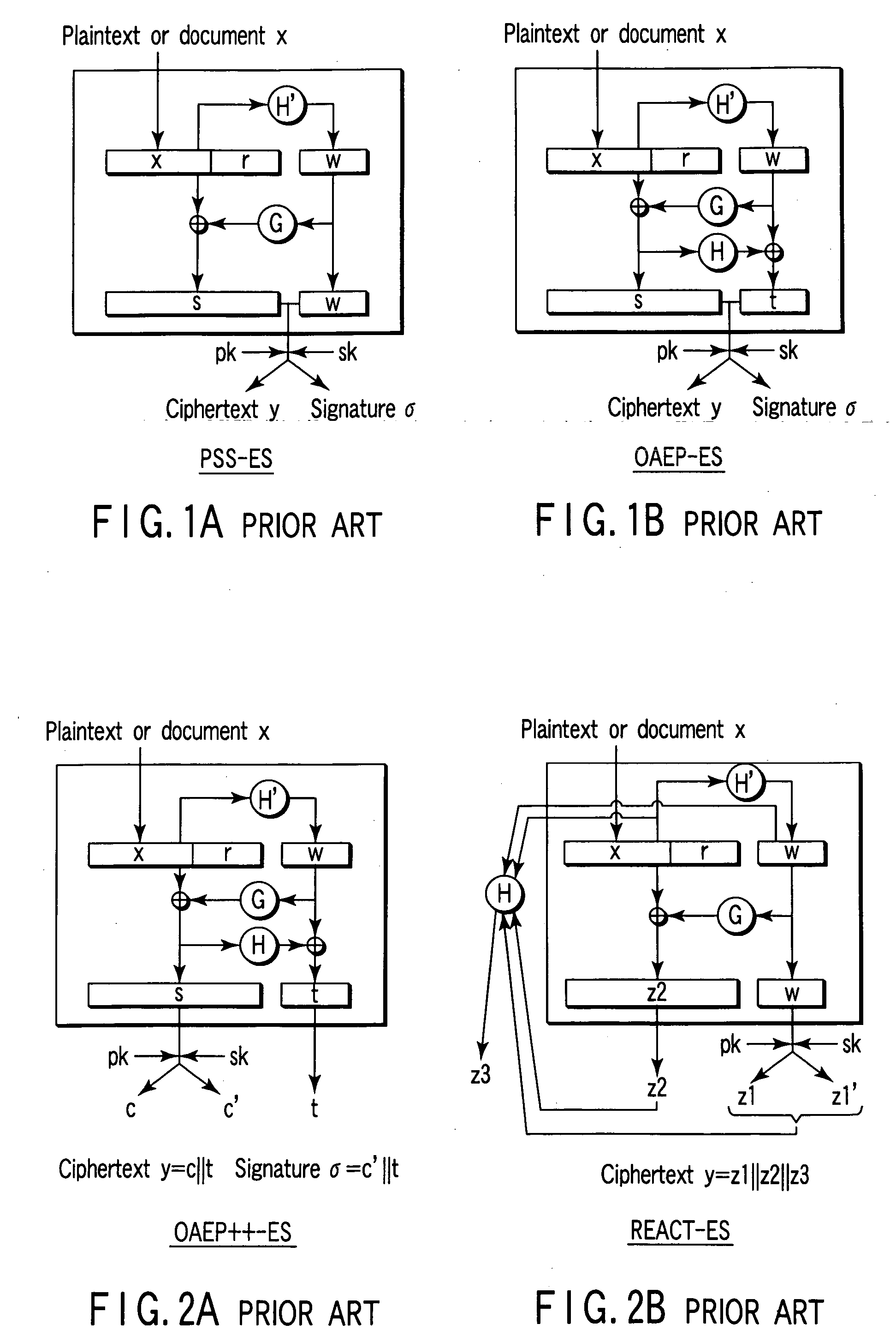
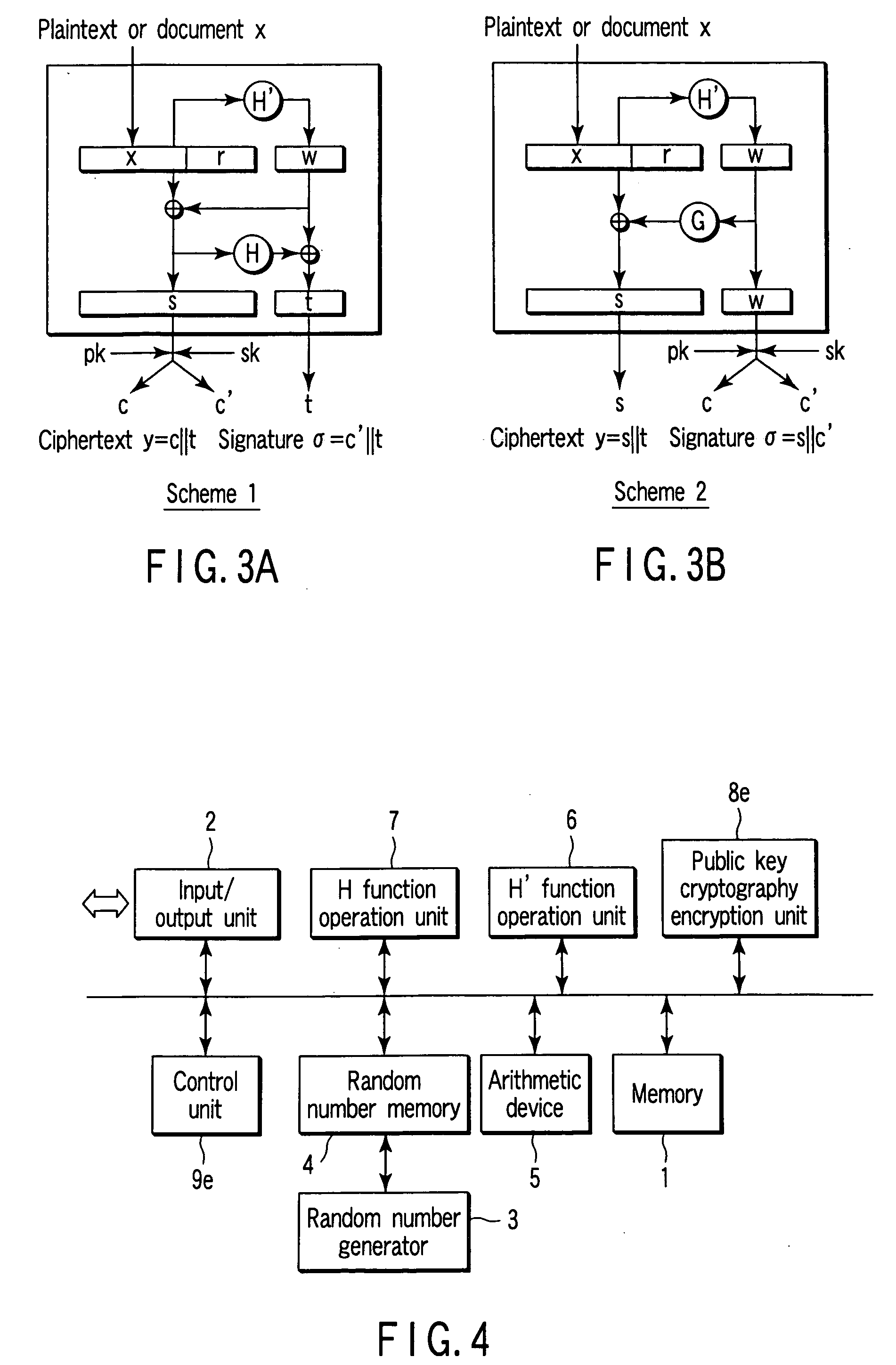
[0037] According to the first and second aspects of the present invention, unlike the conventional PSS-ES scheme (FIG. 1A) or OAEP-ES scheme (FIG. 1B), a ciphertext or signature is created as concatenated data obtained by concatenating two data, as shown in FIG. 3. In addition, the concatenated data is created by using the public key encryption scheme for only one (necessary part) of the data. Hence, tight security for the one-way characteristic of the trapdoor one-way function of the public key encryption scheme can be implemented.

Problems solved by technology

It is difficult to obtain the information about the plaintext x.
More specifically, it is difficult to obtain information about a plaintext without obtaining the inverse function value w=f−1(c).
However, the attacker cannot obtain information about the plaintext.
However, when the PSS-ES scheme is used as an encryption scheme, it cannot present security only with the one-way characteristic.
As described above, the PSS-ES scheme cannot present security depending on the one-way characteristic of the encryption function.
However, the partial-domain one-way function is more restricted than the one-way function.
Even when security can be presented depending on the partial-domain one-way characteristic of the partial-domain one-way function, the encryption scheme cannot be supposed to have tight security.
This increases the key storage area and calculation cost.
However, the encryption scheme or signature scheme cannot be broken without breaking the one-way characteristic of the trapdoor one-way function.

Method used


Image

  • Encryption/signature method, apparatus, and program
  • Encryption/signature method, apparatus, and program
  • Encryption/signature method, apparatus, and program

Examples


first embodiment

[0063]FIG. 4 is a schematic block diagram showing the arrangement of an encryption apparatus according to the first embodiment of the present invention. FIG. 5 is a schematic block diagram showing the arrangement of a decryption apparatus according to the first embodiment. The same reference numerals denote the same elements in these views, and a detailed description thereof will be omitted. Different parts will mainly be described here. This also applies to the remaining embodiments.

[0064] The encryption apparatus comprises a memory 1, input / output unit 2, random number generator 3, random number memory 4, arithmetic device 5, H′ function operation unit 6, H function operation unit 7, public key cryptography encryption unit 8e, and control unit 9e. The elements 1, 2, and 4 to 9e except the random number generator 3 are connected through a bus. The suffix e in the units 8e and 9e represents encryption processing. A suffix d (to be described later) represents decryption processing. ...

second embodiment

[0131]FIG. 8 is a schematic block diagram showing the arrangement of a signature apparatus according to the second embodiment of the present invention. FIG. 9 is a schematic block diagram showing the arrangement of a signature verification apparatus according to the second embodiment.

[0132] This embodiment is a modification to the first embodiment. In the second embodiment, signature processing and signature verification processing using a private key sk are executed in place of encryption processing and decryption processing using the public key pk.

[0133] The signature apparatus has a public key cryptography signature generation unit 8s in place of the public key cryptography encryption unit 8e of the elements 1 to 9e of the encryption apparatus. The signature apparatus also has a control unit 9s for signature processing in place of the control unit 9e for encryption processing. Accordingly, the signature apparatus has a private key memory 10 which can be read-accessed from the p...

third embodiment

[0179]FIG. 11 is a schematic block diagram showing the arrangement of an encryption / signature apparatus according to the third embodiment of the present invention. This embodiment is a combination of the first and second embodiments. The apparatus comprises public key cryptography arithmetic units 8e, 8d, 8s, and 8v capable of executing all the above-described encryption processing, decryption processing, signature processing, and signature verification processing, and control units 9e, 9d, 9s, and 9v corresponding to the arithmetic units.

[0180] According to the above arrangement, encryption / signature apparatus usable for both processing operations of the first and second embodiments can be implemented. The encryption / signature apparatus according to the third embodiment can execute encryption processing (8e and 9e), decryption processing (8d and 9d), signature processing (8s and 9s), and signature verification processing (8v and 9v). However, the present invention is not limited t...


PUM


Abstract

According to each embodiment of the present invention, random function operations less than three times and tight security can simultaneously be implemented. More specifically, a ciphertext y=c∥t or a signature σ=c′∥t is created as concatenated data of two data. The concatenated data is created by using a public key encryption scheme for only one (necessary part s) of the data. For this reason, tight security for the one-way characteristic of a trapdoor one-way function of the public key encryption scheme can be implemented. In addition, the output size of a first random function H′ is limited. Accordingly, a random function G for bit expansion in the conventional. OAEP++-ES scheme can be omitted. Hence, the number of times of use of random functions can be reduced to two.

Description

CROSS-REFERENCE TO RELATED APPLICATIONS [0001] This application is based upon and claims the benefit of priority from prior Japanese Patent Application No. 2004-008840, filed Jan. 16, 2004, the entire contents of which are incorporated herein by reference. BACKGROUND OF THE INVENTION [0002] 1. Field of the Invention [0003] The present invention relates to an encryption / signature method, apparatus, and program which use a public key encryption scheme and, more particularly, to an encryption / signature method, apparatus, and program which can simultaneously implement tight security and random function operations less than three times. [0004] 2. Description of the Related Art [0005] Generally, encryption methods can be classified into secret key encryption schemes and public key encryption schemes. In a public key encryption scheme, key delivery that poses a problem in a secret key scheme can be avoided. [0006] For example, in a public key encryption scheme, each of users A, B, . . . ge...

Claims


Application Information

Patent Timeline
IPC IPC(8): H04L9/00H04L9/30H04L9/32
CPCH04L2209/20H04L9/302H04L2209/08H04L2209/04H04L9/3247
Inventor KOMANO, YUICHIKAWAMURA, SHINICHISHIMBO, ATSUSHI
Owner KK TOSHIBA
Learn More