Adjustable gun rail lock

a gun rail lock and adjustable technology, applied in the field of firearms, can solve the problems of high cost of add-on enhancements, easy loss, non-uniform calibration and weapon sighting, etc., and achieve the effect of simple manufacture and assembly, and reduced down time and operating costs

Active Publication Date: 2010-11-02
AMERICAN DEFENSE MFG
View PDF44 Cites 105 Cited by
  • Summary
  • Abstract
  • Description
  • Claims
  • Application Information

AI Technical Summary

Benefits of technology

[0025]In one embodiment, the accessory may include a high-powered scope, night vision sight, or other such accessory. The accessory sits on top of the gun barrel or the rail mount. The goal is to provide a quick-release mechanism that will not jam up when it gets dirty or is subject to extreme conditions such as hot or cold.
[0029]One object of the invention is to provide an apparatus that is ruggedized and reliable, thereby decreasing down time and operating costs. Another object of the invention is to provide an apparatus that has one or more of the characteristics discussed above but which is relatively simple to manufacture and assemble using a minimum of equipment.

Problems solved by technology

This also results in high cost for the add-on enhancements.
Since the male portion of the Swan / Weaver rail is easily removed by the firearm operator, they are also easily lost and calibration and weapon sighting are difficult and nonuniform.
However, these rails, also, suffer from alignment problems due to the shock created by the gases during firing.
Some of the above devices suffer from a number of disadvantages.
First, conventional mounts are substantially cylindrical in cross-section, such that their bottom surface is curved, so they provide no stability if the weapon is leaned upon a wall, for example.
However, this structure makes it difficult to comfortably grip the weapon while holding the mount, and often places the user's hand in close proximity to the hot barrel during firing.
Thus, this location is often not optimal for users of different heights and different arm lengths.

Method used


Image

  • Adjustable gun rail lock
  • Adjustable gun rail lock
  • Adjustable gun rail lock

Examples


Embodiment Construction

[0058]The present invention and the various features and advantageous details thereof are explained more fully with reference to the non-limiting embodiments described in detail in the following description.

1. System Overview

[0059]The invention solves the problem of having a locking mechanism that automatically locks the scope or other accessory onto a rail mount or rail system. As tolerances of the rail may be off, the locking mechanism of the present invention may be adjusted without the use of specialized tools to maintain a constant tension and add durability.

2. Detailed Description

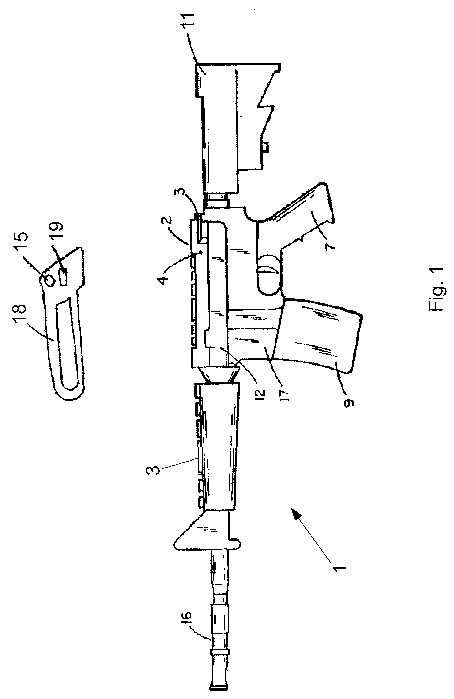
[0060]Referring to the drawings in detail wherein like elements are indicated by like numerals, there is shown in FIG. 1 an outline of a conventional combat firearm 1 having a conventional stock 11, upper receiver 12, lower receiver 17, barrel 16, pistol grip 7, magazine 9, and arced handle 18 is preferably joined to the upper receiver 12. The barrel 16 is also joined to the upper receiver 12, i.e., t...


PUM


Abstract

Systems and methods for mounting accessories to a firearm are disclosed. The systems include a rail connector and quick release device for mounting on a firearm. The connector includes at least one mounting rail and a fastening member for securely fastening the connector directly to the firearm. The quick release is then mounted to the mounting rail.

Description

CROSS-REFERENCE TO RELATED APPLICATIONS[0001]This application claims the benefit of U.S. Ser. Nos. 60 / 884,812, filed Jan. 12, 2007, and 11 / 959,020, filed Dec. 18, 2007, the disclosures of which are hereby incorporated in their entirety by reference.BACKGROUND OF THE INVENTION[0002]1. Field of the Invention[0003]The present invention relates in general to the field of firearms. More particularly, the present invention relates to gun mounts. Specifically, a preferred embodiment of the present invention relates to a quick release-mounting device for a weapon.[0004]2. Discussion of the Related Art[0005]As the field of combat weaponry expands, numerous add-on enhancements have become available for attachment to standard firearms thereby significantly upgrading the capability of the firearm. However, because of the variety of shapes of the upper receivers of different firearms, the add-on enhancements must be modified each time they are sold for a different firearm. This also results in h...

Claims


Application Information

Patent Timeline
Patent Type & Authority Patents(United States)
IPC IPC(8): F41G1/38
CPCF41C27/00F41G11/003
Inventor STORCH, TROYGROSS, JOHNORNE, III, WILLIAMKINCEL, ERIC STEPHEN
Owner AMERICAN DEFENSE MFG
Why Eureka
Try Eureka