Dual clutch pack dual operating clutch and method for adjusting same

a dual-operating, clutch technology, applied in the direction of friction clutches, mechanical equipment, assembly machines, etc., can solve the problems of inability to completely inability to disclose the adverse effects of wear and overheating, and inability to fully smooth the transition between various transmission gears. to achieve the effect of smooth torque transfer and reducing wear and degradation

Inactive Publication Date: 2010-11-02
SCHAEFFLER TECH AG & CO KG
View PDF25 Cites 17 Cited by
  • Summary
  • Abstract
  • Description
  • Claims
  • Application Information

AI Technical Summary

Benefits of technology

[0007]In accordance with the present invention a dual automatic mechanically actuated wet clutch device is provided for a dual input shaft transmission that includes tightly specified spacings or gaps between friction plate surfaces and control mechanisms for controlling such spacing during operation. The dual clutch system functions well for smoothly transferring torque from an engine through a dual input shaft transmission to drive wheels. The tightly specified friction surface spacing and apparatus and method for obtaining and maintaining it permit consistent clutch operation with respect to mechanical travel and engagement pressure. The wet clutch surfaces reduce wear and degradation due to friction.
[0020]The friction plates of the second clutch pack are movable toward each other along their respective drive and driven rings so as to engage each other on their surfaces so as to enable the transfer of torque from the second drive ring to the second driven ring without significant slippage between adjacent friction plates.
[0024]adjusting tolerance from the main clutch bearing to a touch point between the outer fulcrum and the outer lever spring to permit a normally open spacing between friction surfaces of between 0.05 and 0.25 mm, preferably at a variance between spacings at least as good as ±0.1 mm and more preferably as good as ±0.05 mm, and to permit sufficient pressure on the friction surfaces during engagement to prevent significant slippage during torque transfer; and
[0025]adjusting tolerance from the main clutch bearing to an inner touch point between the inner fulcrum and the inner lever spring to permit a normally open spacing between inner friction surfaces of between 0.05 and 0.25 mm, preferably at a variance between spacings at least as good as ±0.1 mm and more preferably at least as good as ±0.05 mm and to permit sufficient pressure on the friction surfaces during engagement to prevent significant slippage during torque transfer.

Problems solved by technology

Such systems have had serious disadvantages since the engine becomes entirely disengaged from the drive wheels when shifting occurs within a transmission between the clutch and the drive wheels.
Completely smooth transition between various transmission gears is thus not possible.
Such known systems, nevertheless have had serious disadvantages.
Furthermore, this patent discloses nothing as to how adverse effects of wear and overheating, due to friction between clutch surfaces during torque transfer changes, might be reduced.
A problem with the systems described in this patent publication is that there is no disclosure or suggestion of desired clutch friction plate spacings and certainly no discussion or suggestion of how to avoid significant variability between friction plate spacing yielding clutch packs that are either too tight causing significant wear and heat at friction surfaces or are too loose causing slippage and / or requiring significant mechanical travel before engagement can occur.
Extreme variability within such dual clutch apparatus and between such different apparatus can thus be common, making fitting into assembly line operation extremely difficult and frequently unacceptable and causing undesirable variability between resulting products.

Method used


Image

  • Dual clutch pack dual operating clutch and method for adjusting same
  • Dual clutch pack dual operating clutch and method for adjusting same
  • Dual clutch pack dual operating clutch and method for adjusting same

Examples


Embodiment Construction

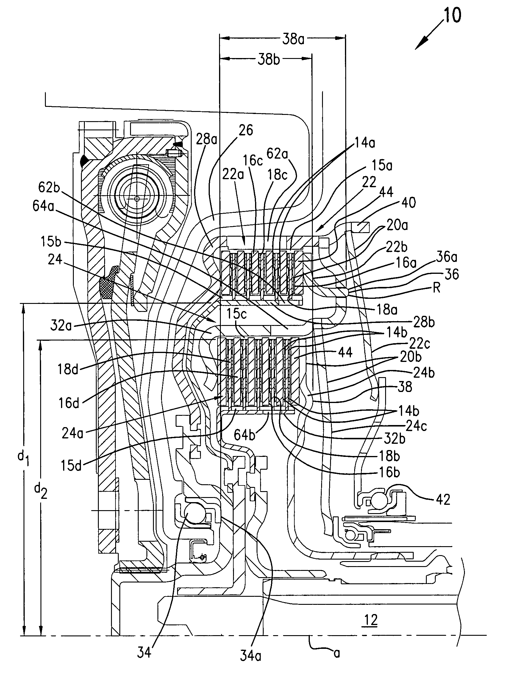
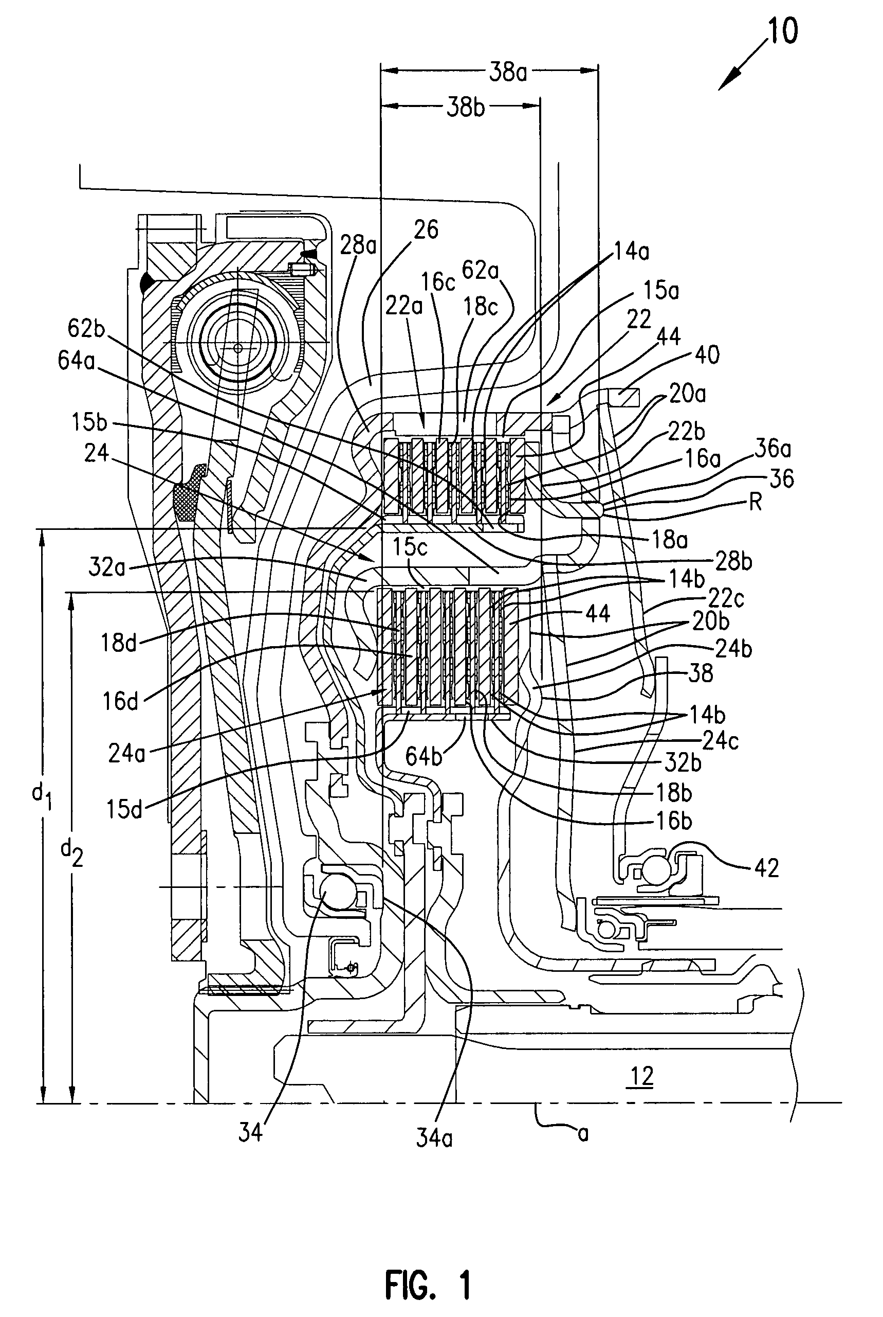
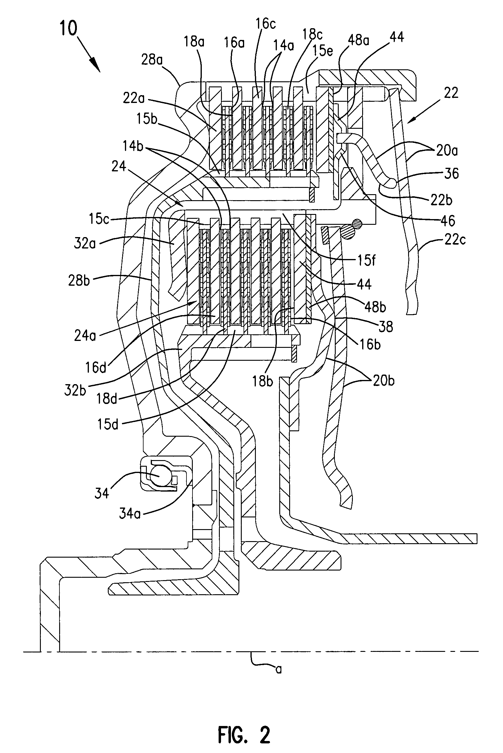
[0035]As previously discussed, the present invention includes a dual automatic mechanically actuated wet clutch device for a dual input shaft transmission that includes tightly specified spacing between friction plate surfaces. The dual clutch system functions well for smoothly transferring torque from an engine through a dual input shaft transmission to drive wheels. The tightly specified friction surface spacing and apparatus and method for obtaining and maintaining it permit consistent clutch operation with respect to mechanical travel and engagement pressure. The wet clutch surfaces reduce wear and degradation due to friction. Further, and unexpectedly, it has been found that fluid in the wet clutch can be used for maintaining a relatively uniform gap distance between the surfaces by means of causing the fluid to flow between the gaps using centrifugal force generated by rotation of the clutch when force is sufficiently reduced so that the surfaces are not held together.

[0036]In...


PUM

PropertyMeasurementUnit
diameteraaaaaaaaaa
frictionaaaaaaaaaa
torqueaaaaaaaaaa

Abstract

A dual automatic mechanically actuated wet clutch device, for operation within a fluid tight housing, for a dual input shaft transmission that includes tightly specified average spacing between friction plate surfaces where the average spacing is selected from between about 0.05 mm to about 0.25 mm in an open position. The clutch has at least first and second independently actuatable clutch portions, and at least one clutch pack in the first or second clutch portion; and mechanical apparatus provided to move friction plates in at least one of the clutch portions toward each other so that they engage. The invention also includes apparatus and methods for adjusting and maintaining the spacing between the friction plate surfaces.

Description

[0001]This application claims the benefit under 35 U.S.C. §119(e) of the following U.S. Provisional Applications, all filed on Feb. 22, 2006: U.S. Provisional Application No. 60 / 775,619; U.S. Provisional Application No. 60 / 775,622; U.S. Provisional Application No. 60 / 775,623; U.S. Provisional Application No. 60 / 775,621; and U.S. Provisional Application No. 60 / 775,620.BACKGROUND OF THE INVENTION[0002]This invention relates to clutches and clutch systems for transferring torque from an engine to a transmission system and more particularly relates to a clutch system for use in vehicles, e.g. in automobiles and trucks.[0003]Most such systems are single clutch systems, i.e. a single clutch is either engaged or disengaged to cause transfer of essentially all torque from an engine to drive wheels when the clutch is closed or none of it when the clutch is open. Such systems have had serious disadvantages since the engine becomes entirely disengaged from the drive wheels when shifting occurs...

Claims


Application Information

Patent Timeline
Patent Type & Authority Patents(United States)
IPC IPC(8): F16D21/06F16D13/75
CPCF16D13/52F16D21/06Y10T29/49904F16D2250/00F16D2021/0676
Inventor UHLER, ADAMGEORGE, PHILIPSTURGIN, TODDHEMPHILL, JEFFREYIZSO, GABORLINDEMANN, PATRICK
Owner SCHAEFFLER TECH AG & CO KG
Why Eureka
Try Eureka