
Mineral water bucket water filling bucket opening sealing device

A sealing device and mineral water technology, applied in the direction of threaded bottle caps, etc., can solve the problems of unstable packaging quality, long packaging time, and low productivity, and achieve the effects of simple structure, stable transmission torque, and convenient use

Inactive Publication Date: 2017-06-09
王柳杨
View PDF0 Cites 0 Cited by
  • Summary
  • Abstract
  • Description
  • Claims
  • Application Information

AI Technical Summary

Problems solved by technology

[0002] At present, the existing device directly uses double-sided laminated aluminum platinum as the inner cover. If the heating and installation of the inner and outer sealing films and packaging films in the above structure are still performed manually, it will inevitably result in long packaging time and low productivity. And the packaging quality is not stable

Method used


Image

  • Mineral water bucket water filling bucket opening sealing device

Examples


Embodiment 1

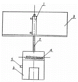
[0010] like figure 1 As shown, the technical scheme of the present invention is: a barrel mouth sealing device for mineral water barrels, which is characterized in that it includes a cylinder, a piston rod, a working head bracket, a bearing socket, a magnetic field coil, a steam inlet, a driven disk socket, a transmission a rotating shaft and a working head; the transmission rotating shaft is sleeved and installed in the end of the power input shaft through a bearing, the driven disk is sleeved and fixed on the transmission rotating shaft, and the rotating head mechanism fixing seat is installed outside the driven disk end face.

[0011] To further illustrate, the working head is threadedly connected and fixed with the piston rod of the cylinder, the working head is in the shape of a cup, and the working head bracket is used for fixing the cylinder.

[0012] To further illustrate, the upper cavity is provided with a magnetic field coil, the magnetic field coil is externally c...

Embodiment 2

[0014] like figure 1 As shown, the technical scheme of the present invention is: a barrel mouth sealing device for mineral water barrels, which is characterized in that it includes a cylinder, a piston rod, a working head bracket, a bearing socket, a magnetic field coil, a steam inlet, a driven disk socket, a transmission a rotating shaft and a working head; the transmission rotating shaft is sleeved and installed in the end of the power input shaft through a bearing, the driven disk is sleeved and fixed on the transmission rotating shaft, and the rotating head mechanism fixing seat is installed outside the driven disk end face.

[0015] To further illustrate, the working head is threadedly connected and fixed with the piston rod of the cylinder, the working head is in the shape of a cup, and the working head bracket is used for fixing the cylinder.

[0016] To further illustrate, the upper cavity is provided with a magnetic field coil, the magnetic field coil is externally c...


PUM


Abstract

The invention discloses a sealing device for the mouth of a mineral water barrel, which is characterized in that it comprises a cylinder, a piston rod, a working head bracket, a bearing sleeve, a magnetic field coil, a steam inlet, a driven disk cover, a transmission shaft, and a working head; The transmission rotating shaft is installed in the end of the power input shaft through a bearing socket, the driven disk is socketed and fixed on the transmission rotating shaft, and the rotating head mechanism fixing seat is installed on the outer end surface of the driven disk; the working head It is threadedly connected and fixed with the piston rod of the cylinder, the working head is cup-shaped, the working head bracket is used for fixing the cylinder, the upper chamber is provided with a magnetic field coil, and the magnetic field coil is externally connected with a magnetic field generator, and the lower chamber is provided with There is a steam inlet, which is externally connected with a steam generator. The invention has the advantages of simple structure and convenient use, and realizes cap screwing torque by adjusting the magnitude of the magnetic force, and the transmission torque is relatively stable.

Description

technical field [0001] The invention belongs to the field of container packaging and sealing, and particularly relates to a sealing device for the mouth of a mineral water barrel. Background technique [0002] At present, the existing device directly uses double-sided laminated aluminum platinum for the inner cover. In the above structure, the heating and installation of the inner and outer sealing films and packaging films are still manually operated, which will inevitably result in long packaging time and low productivity. And the packaging quality is not stable. SUMMARY OF THE INVENTION [0003] In view of the deficiencies in the prior art, the purpose of the present invention is to provide a sealing device for the mouth of a mineral water barrel. [0004] The technical scheme of the present invention is: a barrel mouth sealing device for mineral water barrels, which is characterized in that it includes a cylinder, a piston rod, a working head bracket, a bearing socket...

Claims


Application Information

Patent Timeline
Patent Type & Authority Applications(China)
IPC IPC(8): B67B3/20
CPCB67B3/20
Inventor 王柳杨
Owner 王柳杨
Learn More