
Semiconductor device having a plurality of stacked transistors and method of fabricating the same

a technology of stacked transistors and semiconductor devices, which is applied in the direction of semiconductor devices, electrical appliances, transistors, etc., can solve the problem of still limiting the degree of integration of semiconductor devices having bulk transistors, and achieve the effect of improving driving ability

Inactive Publication Date: 2010-11-02
SAMSUNG ELECTRONICS CO LTD
View PDF12 Cites 14 Cited by
  • Summary
  • Abstract
  • Description
  • Claims
  • Application Information

AI Technical Summary

Benefits of technology

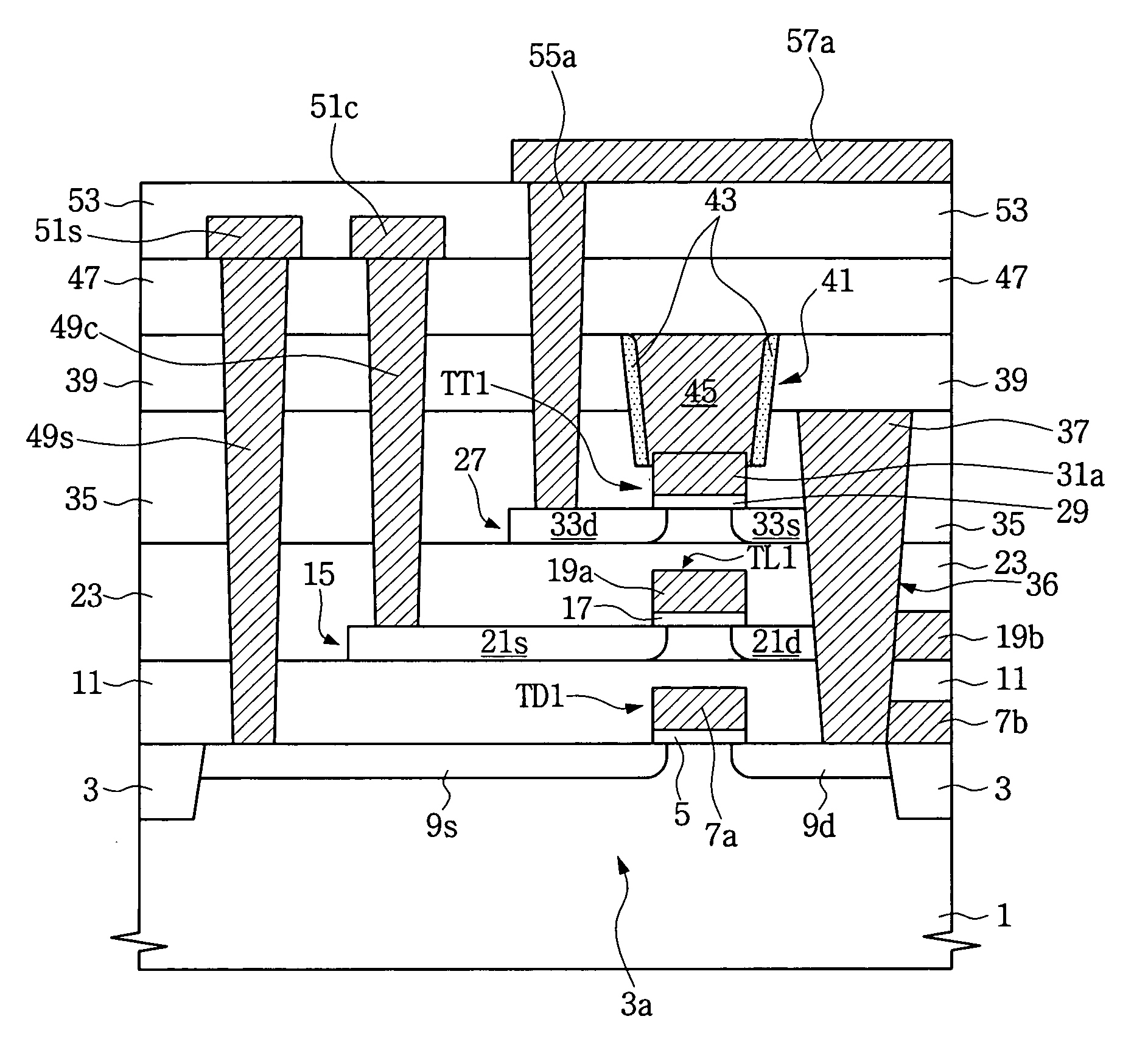
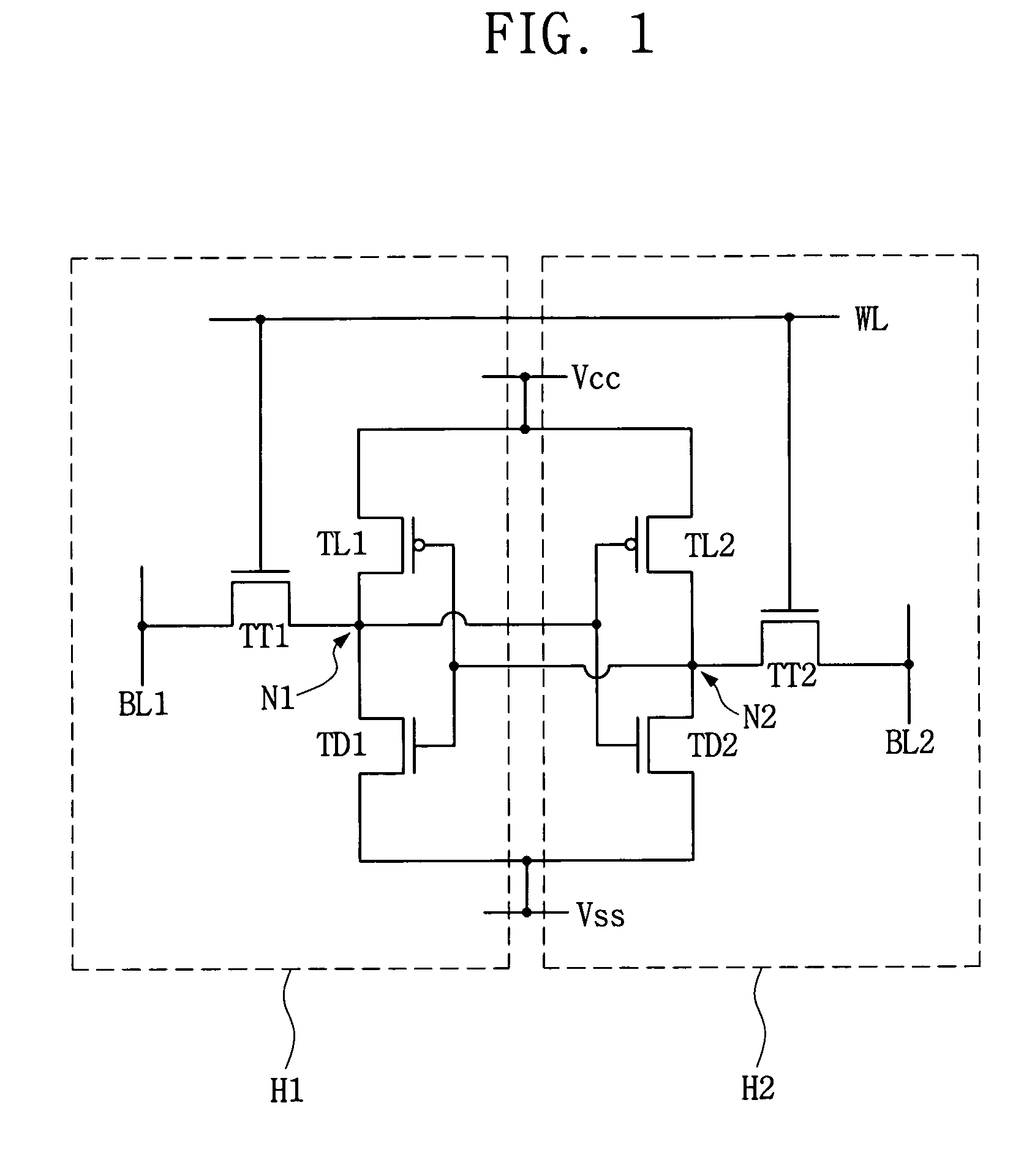
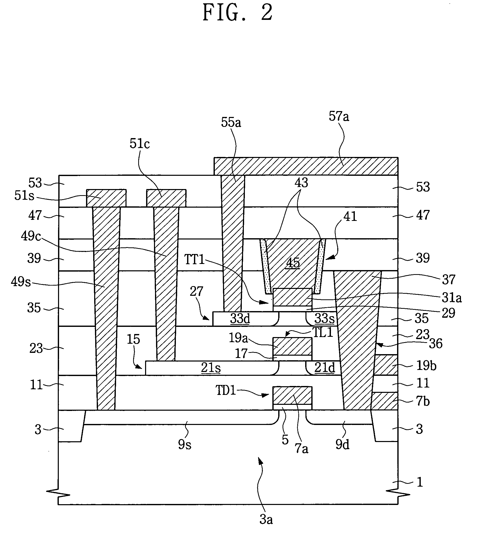
The patent text describes a semiconductor device with stacked thin film transistors (TFTs) and a method of fabricating it. The device includes a lower insulating layer on a semiconductor substrate and an upper channel body pattern on the lower insulating layer. A non-metal transfer gate electrode is formed on the upper channel body pattern and is covered by an intermediate insulating layer. A metal word line is formed on the intermediate insulating layer and contacts the non-metal transfer gate electrode. An insulating spacer covers the sidewall of the metal word line. The method includes forming the non-metal transfer gate electrode, intermediate insulating layer, metal word line, insulating spacer, and metal node plug. The device and method improve driving ability and allow for more efficient fabrication.

Problems solved by technology

Although the size of bulk transistors have been reduced from improvements in photolithography, there is still a limit for increasing the degree of integration of semiconductor devices having bulk transistors arranged in a two-dimensional manner on a semiconductor substrate.

Method used


Image

  • Semiconductor device having a plurality of stacked transistors and method of fabricating the same
  • Semiconductor device having a plurality of stacked transistors and method of fabricating the same
  • Semiconductor device having a plurality of stacked transistors and method of fabricating the same

Examples


Embodiment Construction

[0024]It will be understood that when an element or layer is referred to as being “on”, “connected to”, “coupled to”, or “covering” another element or layer, it may be directly on, connected to, coupled to, or covering the other element or layer or intervening elements or layers may be present. In contrast, when an element is referred to as being “directly on,”“directly connected to,” or “directly coupled to” another element or layer, there are no intervening elements or layers present. Like numbers refer to like elements throughout the specification. As used herein, the term “and / or” includes any and all combinations of one or more of the associated listed items.

[0025]It will be understood that, although the terms first, second, third, etc. may be used herein to describe various elements, components, regions, layers, and / or sections, these elements, components, regions, layers, and / or sections should not be limited by these terms. These terms are only used to distinguish one elemen...


PUM


Abstract

A semiconductor device according to example embodiments may have a plurality of stacked transistors. The semiconductor device may have a lower insulating layer formed on a semiconductor substrate and an upper channel body pattern formed on the lower insulating layer. A source region and a drain region may be formed within the upper channel body pattern, and a non-metal transfer gate electrode may be disposed on the upper channel body pattern between the source and drain regions. The non-metal transfer gate electrode, the upper channel body pattern, and the lower insulating layer may be covered by an intermediate insulating layer. A metal word line may be disposed within the intermediate insulating layer to contact at least an upper surface of the non-metal transfer gate electrode. An insulating spacer may be disposed on a sidewall of the metal word line. A metal node plug may be disposed within the intermediate insulating layer and the lower insulating layer to contact the source region of the upper channel body pattern. Example embodiments also relate to a method of fabricating the above semiconductor device.

Description

PRIORITY STATEMENT[0001]This application claims the benefit under 35 U.S.C. §119 to Korean Patent Application No. 10-2007-0072964, filed on Jul. 20, 2007 with the Korean Intellectual Property Office (KIPO), the entire contents of which are incorporated herein by reference.BACKGROUND[0002]1. Technical Field[0003]Example embodiments relate to a semiconductor device and a method of fabricating the same.[0004]2. Description of the Related Art[0005]A conventional semiconductor device has a plurality of bulk transistors which use the semiconductor substrate as a channel body layer. Consequently, the size of the bulk transistors must be reduced to increase the degree of integration. Although the size of bulk transistors have been reduced from improvements in photolithography, there is still a limit for increasing the degree of integration of semiconductor devices having bulk transistors arranged in a two-dimensional manner on a semiconductor substrate.SUMMARY[0006]Example embodiments relat...

Claims


Application Information

Patent Timeline
Patent Type & Authority Patents(United States)
IPC IPC(8): H01L27/12H10B10/00
CPCH01L21/8221H01L27/0688H01L27/1108H01L27/1207H10B10/125H10B10/00
Inventor PARK, HAN-BYUNGJUNG, SOON-MOONLIM, HOONYEO, CHA-DONGSON, BYOUNG-KEUNSHIM, JAE-JOOHONG, CHANG-MIN
Owner SAMSUNG ELECTRONICS CO LTD
Learn More